
Millenia V6-2255cc 2.3L DOHC (1995)
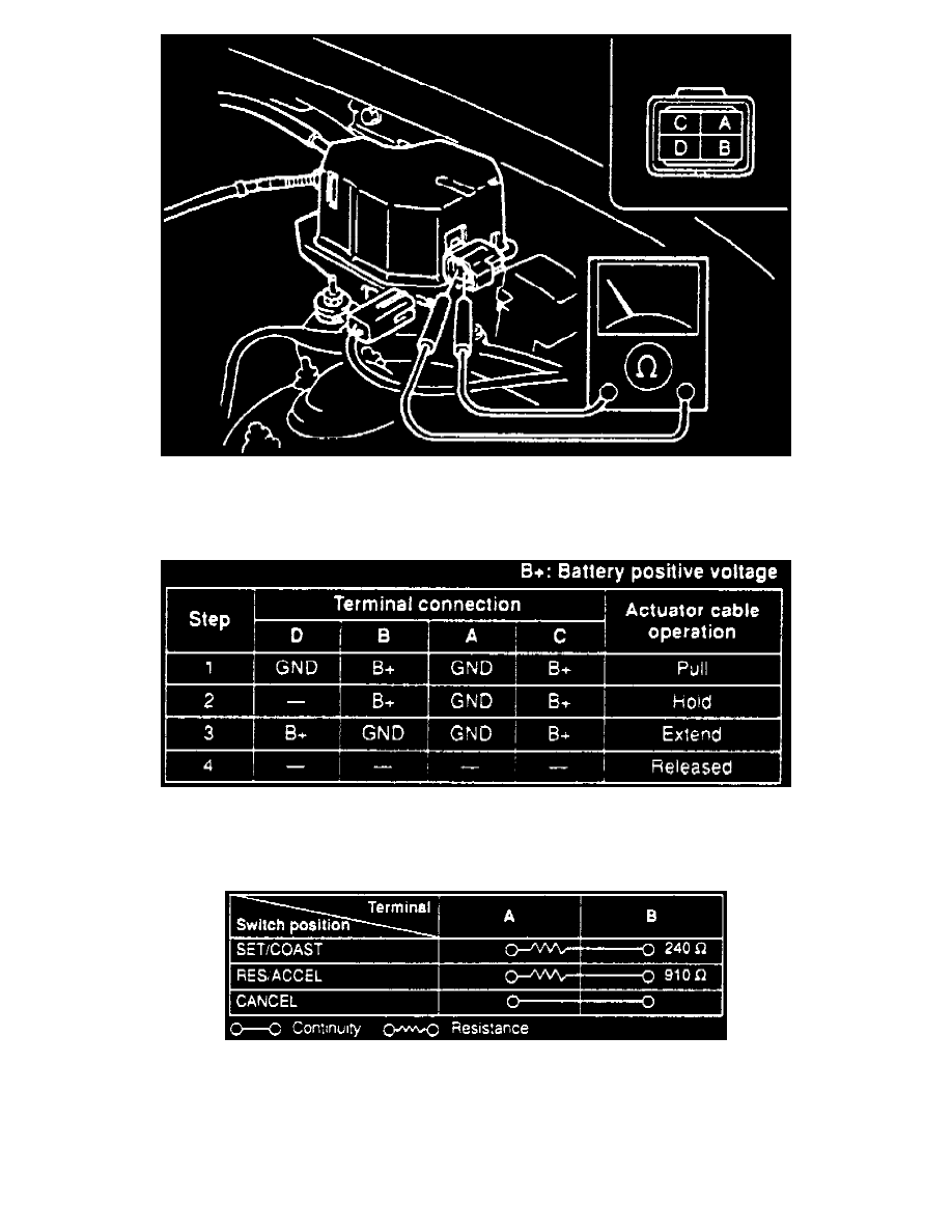
Fig. 38 Cruise Control Actuator Location & Terminal Identification
2. If resistance between terminals A and C is not 14.4 ohms or resistance between terminals B and D is not 10.2 ohms, replace actuator.
3. Connect B+ and ground to terminals as shown in Fig. 39 and ensure actuator cable operation is as specified. If it is not, replace actuator.
Fig. 39 Cruise Control Actuator Inspection
CRUISE CONTROL SWITCH
Ensure continuity between switch terminals is as specified in Fig. 40. If it is not, replace switch.
Fig. 40 Cruise Control Switch Inspection