
Millenia L V6-2.5L DOHC (1997)
Steering Column Position Sensor: Testing and Inspection
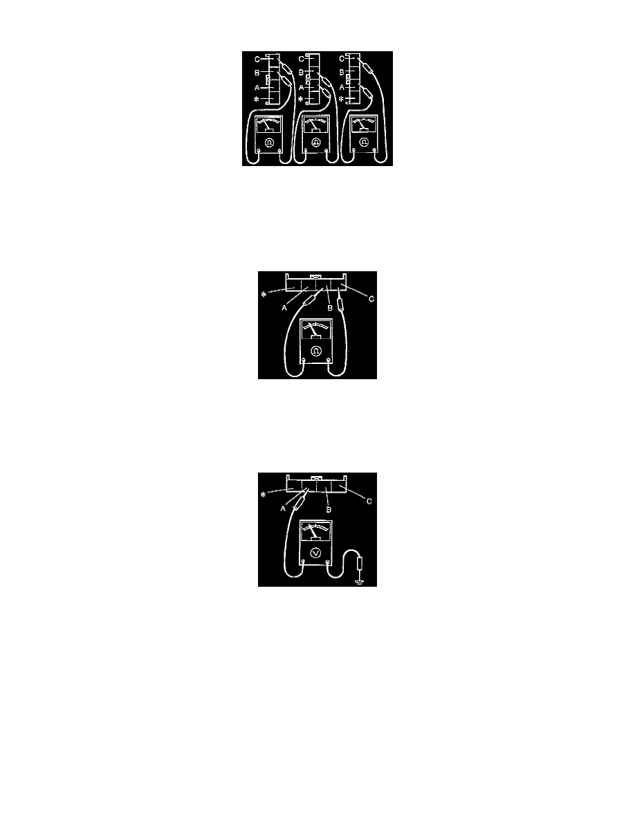
CONTINUITY INSPECTION
1. Disconnect the connectors between the tilt sensor and the CPU.
2. Check for continuity between each pair [(A)-(B), (B)-(C), (A)-(C)] of the three terminals [(A), (B), (C)] of the tilt sensor side connector. There
should be continuity between all connectors.
3. If not as specified, replace the steering shaft assembly.
CAUTION: When using the ohmmeter, always make sure that no voltage is applied. If voltage is applied, the ohmmeter may be damaged.
RESISTANCE INSPECTION
1. Disconnect the connectors between the tilt sensor to the CPU.
2. Measure the resistance between terminal (B) and terminal (C) of the tilt sensor side connector.
3. If the resistance is not approximately 1 kilo ohm, replace the steering shaft assembly.
VOLTAGE INSPECTION
At Top Dead Point Position In Away Auto Control
1. Insert the ignition key into the key cylinder (LOCK position).
2. Turn ON the auto switch.
3. Remove the ignition key from the key cylinder to make the steering wheel rise to the top dead point position.
4. Leave the connectors connected. Connect the (+) terminal of the voltmeter to the tilt sensor side connector's variable resistance pole side
terminal, (A), (at the back of the connector), and connect the voltmeter's (-) terminal to the body ground side of the connector.
5. If voltage is not approximately 4.6 volts, replace the steering shaft assembly.