
MPV L4-2606cc 2.6L SOHC (1989)
Air Flow Meter/Sensor: Testing and Inspection
Burn-Off Control System
1.
Remove the rubber boot from the air flow sensor connector.
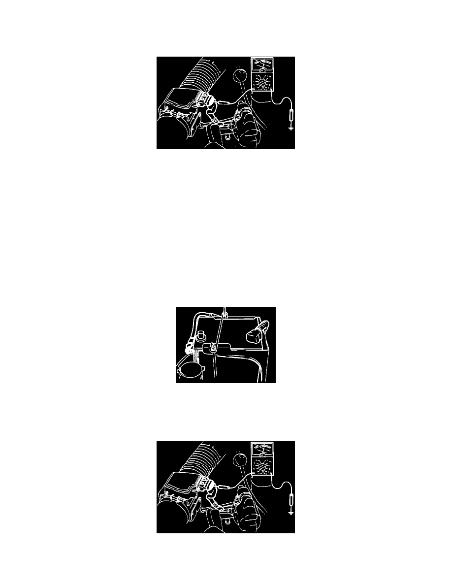
Air Flow Meter Voltage Testing
2.
Check the terminal voltages with a voltmeter and compare them to the chart below.
CONDITION
IGNITION ON
ENGINE RUNNING
TERMINAL WIRE
B/W (Power supply) Approx. 12 volts
Approx. 12 volts
G/O (Burn-off)
0 volts
0 volts
G/B (Air flow mass)
1.0-2.0 volts
1.9-5 volts
B/W (Ground)
Approx. 0 volts
Approx 0 volts.
B/O (Ground)
Approx. 0 volts
Approx 0 volts.
3.
If not as specified, check the wiring harness for an open or short circuit. If a fault is found in the wiring harness, correct the problem. Otherwise,
proceed with step 4.
Negative Battery Terminal Disconnected
4.
Disconnect the negative battery terminal and reconnect it.
5.
Warm up the engine to normal operating temperature.
6.
Run the engine for three minutes at approx. 2,000 rpm in neutral.
Air Flow Meter Voltage Testing
7.
Turn the ignition switch off and check the voltage at the airflow sensor terminal wire (G/O) and terminal (2K) of the engine control unit. The