
MPV 2WD V6-3.0L SOHC (1992)
Engine Control Module: Testing and Inspection
ECU Testing
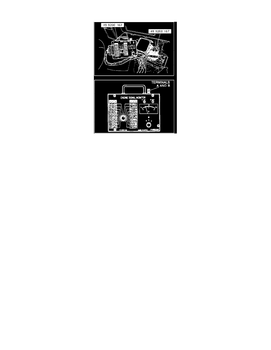
The Mazda Engine Signal Monitor (#49 9200 162) is utilized to check ECU terminal voltages. This tool inspects individual terminal voltages as
selected with the monitor switch. A high impedance volt/ohm meter can also be used to check these voltages. Aftermarket test units are available that
will read ECU terminal voltages when connected with proper adapters.
To use the Engine Signal Monitor, connect unit between ECU and wiring harness with the correct adapter (#49 9200 167). Turn select and monitor
switches to the desired terminal number for a voltage readout. Conduct tests with engine at operating temperature unless instructed otherwise.
CAUTION:Never apply voltage to terminals "A" and "B."
ECU TESTING PRECAUTIONS [1]
1.
If factory test equipment is not available, use only digital volt/ohm meter with minimum 10Meg ohms internal impedance for testing ECU terminal
voltages.
2.
Never push circuit tester probes into connectors from ECU side.
3.
Before replacing an ECU, check components, wiring harnesses and terminal contacts. If terminal voltage readings are incorrect, check for other
possible causes (lower than normal or zero voltage may indicate a short to ground in wiring. Higher than normal voltage may indicate an open
circuit in wiring between that terminal and the corresponding input/output device, or a poor connection within a harness connector.) Repair as
needed and recheck voltage readings.
[1]
For more complete information on special precautions regarding handling and testing of electronic components, refer to Service Precautions.
ECU PIN VOLTAGE CHART
PART 1