
MPV DX V6-2.5L DOHC (2000)
EGR Boost Sensor: Testing and Inspection
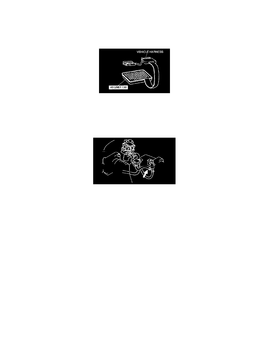
Using the SST (104 Pin Breakout Box)
NOTE: Perform the following test only when directed.
1. Turn the ignition switch to LOCK.
2. Disconnect the PCM connector.
3. Connect the SST (104 Pin Breakout Box).
4. Tighten the connector attaching bolt.
Tightening torque
7.9 - 10.7 N.m {80 - 110 kgf.cm, 69.5 - 95.4 in.lbf}
5. Turn the ignition switch to ON.
6. Disconnect the vacuum hose between the EGR boost sensor and the EGR boost sensor solenoid valve.
7. Verify that the 104 pin Breakout Box terminal 34 voltage is within the specification.
Specification
Measurement voltage: 2.3 - 4.7 V
CAUTION: Do not apply vacuum more than specified. Doing so will damage the EGR boost sensor.
8. Apply vacuum of -26.6 kPa {-200 mmHg, -7.85 inHg} to the EGR boost sensor and verify that 104 pin Breakout Box terminal 34 voltage
difference from Step 7 as specified.
-
If not as specified, perform the "Circuit Open/Short Inspection".
Specification
Voltage difference: 0.8 - 1.3 V