
MPV ES V6-2.5L DOHC (2001)
Terminal Voltage Table (Reference)
(Engine is idling, and SST is connected unless indicated otherwise)
*1: Use this terminal at factory only, not used for inspection and repair at field location
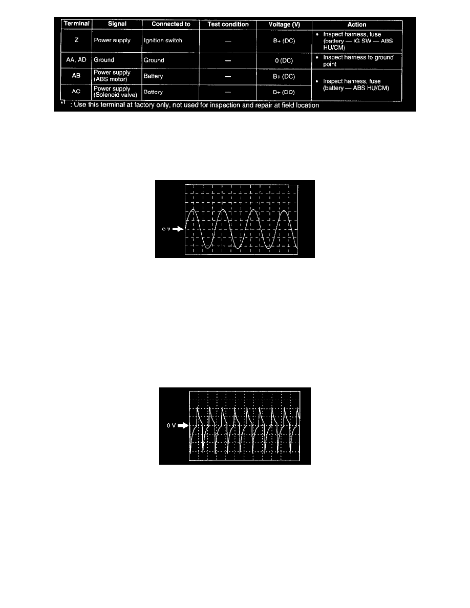
Inspection Using An Oscilloscope (Reference)
Wheel speed
-
ABS HU/CM terminal:
RF: G (+) - D (-)
RR: A (+) - B (-)
LF: I (+) - E (-)
LR: C (+) - F (-)
-
Oscilloscope setting: 1 V/DIV (Y), 2 ms/DIV (X)
-
Vehicle condition: Driving 30 km/h [18.6 mph]
Note:
-
As vehicle speed increase, period of wave shorten.
-
If malfunctioning in the sensor rotor, wave profile warp.
Vehicle speed output
-
ABS HU/CM terminal:Q(+)-AA(-)
-
Oscilloscope setting: 2 V/DIV (Y), 25 ms/DIV (X)
-
Vehicle condition: Driving 25 km/h [15.5 mph]
Note: As vehicle speed increase, period of wave shorten.