
MPV ES V6-2.5L DOHC (2001)
1. Turn the ignition switch to ON.
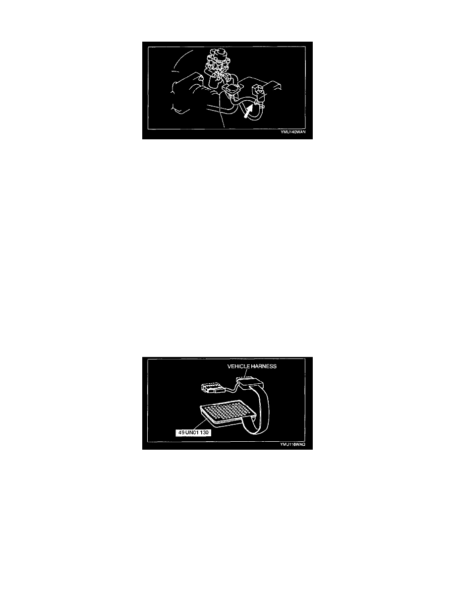
2. Disconnect the vacuum hose between the EGR boost sensor and the EGR boost sensor solenoid valve.
3. Set the NGS tester and monitor the BARO V PID.
4. Verity that the BARO V PID is within the specification.
NOTE
-
The output voltage varies with the following condition.
-
Input voltage 4.5 - 5.5 V
-
Outside temperature 10 - 50 °C {50 - 122 °F}
-
Sea level -200 - 3,000 m {-656 - 9,840 ft}
Specification
BARO V: 2.3 - 4.7 V
CAUTION: Do not apply vacuum out of specification. Doing so will damage the EGR boost sensor.
5. Apply the vacuum of -26.6 kPa {-200 mmHg, -7.85 inHg} to EGR boost sensor and verity that the BARO V PID varies from Step 4 as specified.
-
If not as specified, perform the "Circuit Open/Short Inspection".
Specification
BARO V variation: 0.8 - 1.3 V
Circuit Open/Short Inspection
1. Disconnect the PCM connector.
2. Connect the SST (104 Pin Breakout Box) with the PCM disconnected.
3. Tighten the connector attaching bolt.
Tightening torque
3.0 - 5.4 N.m {30 - 56 kgf.cm, 27 - 48 in.lbf}