
MPV ES 4WD V6-3.0L SOHC (1997)
NOTE:
-
The indicator lights of the SST (Monitor, Engine Signal), provided for confirmation of the voltmeter range, is also used for detection of the pulse
such as the fuel injector control signal, which is difficult to detect by using the voltmeter.
-
Terminals A and B of the SST (Monitor, Engine Signal) are for connection of an external instrument. By connecting an external instrument such as
a circuit tester or an oscilloscope, various inspections in addition to the measurement of the PCM terminal voltages are made possible.
With SST-New Generation Star Tester
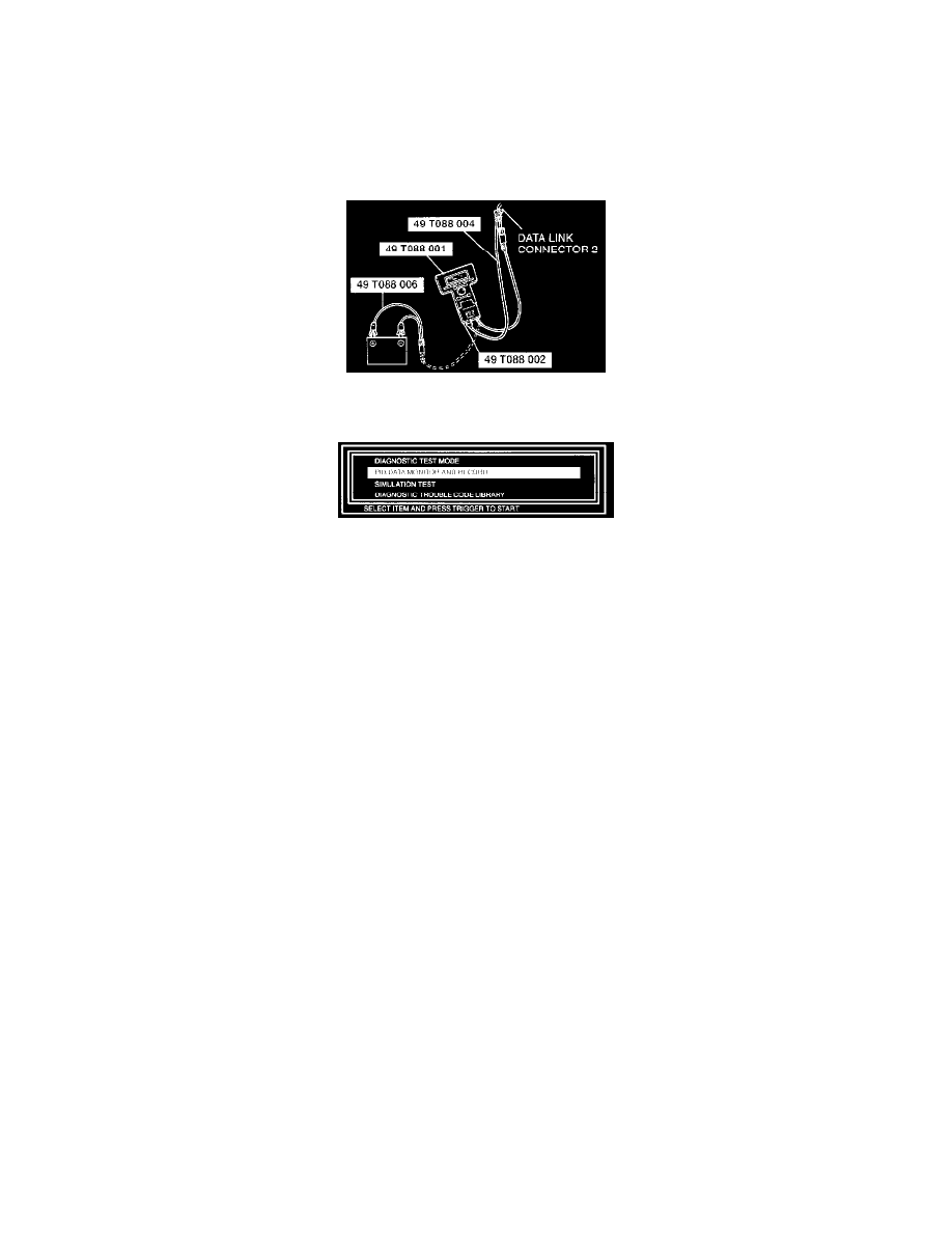
1. In the passenger compartment, connect the Special Service Tools (SST)s New Generation Star (NGS) tester to the data link connector 2 located
under the driver side dashboard.
2. Referring to the NGS operational manual, select the "PID/DATA MONITOR AND RECORD" function.
3. Inspect each PCM input/output signal.
NOTE: The "PID/DATA MONITOR AND RECORD" function is to monitor the calculation value of input/output signals in the PCM. Deviation
in the value does not always indicate malfunction in the related input/output devices (sensors and solenoids).
4. If normal output signal cannot be detected when all input signals are normal, replace the PCM.