
MPV LX V6-2.5L DOHC (2000)
-
Main relay
1. Connect the NGS tester to the DLC-2.
2. Turn the ignition switch to ON.
3. Select the "PID/DATA MONITOR AND RECORD" function on the NGS display and press TRIGGER.
4. Select the appropriate PID on the NGS display and press START.
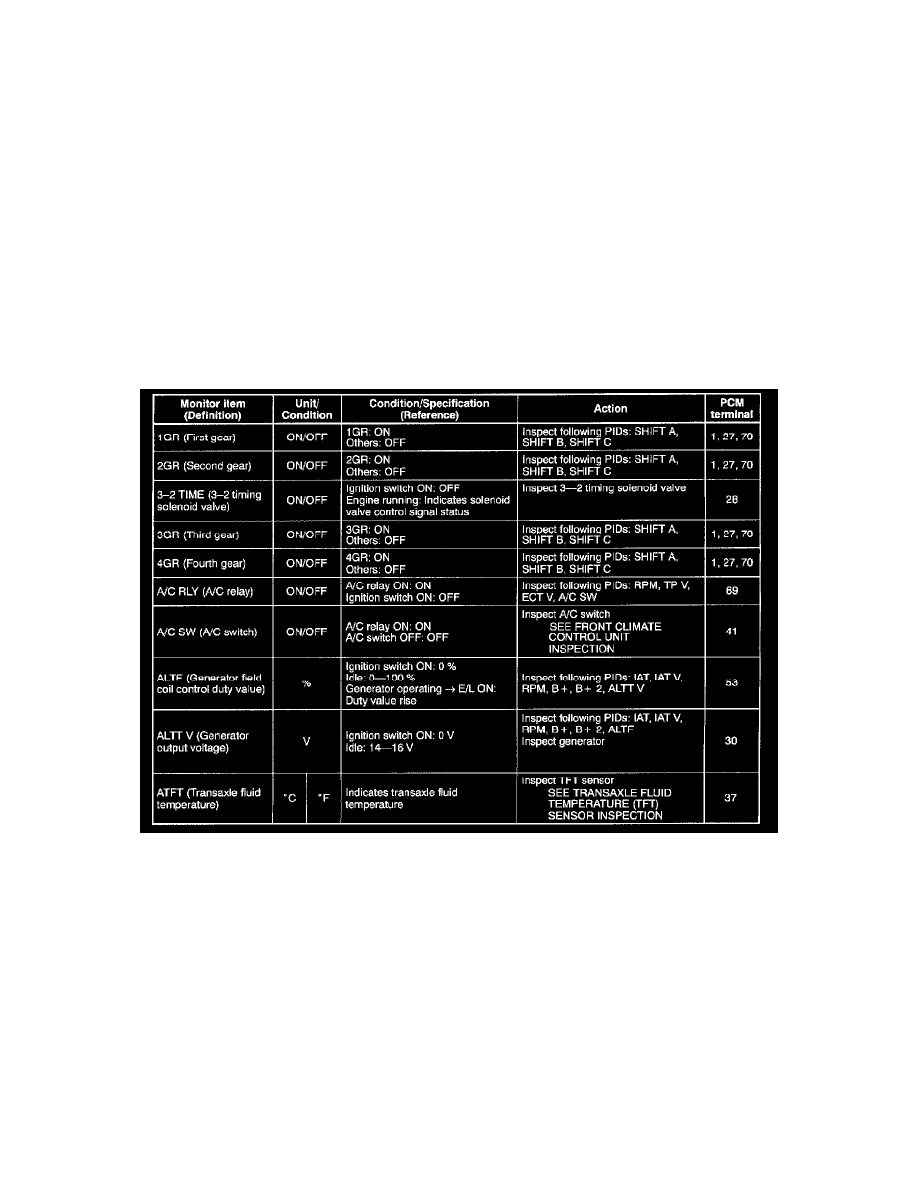
5. Measure the PID value.
-
If PID value is not within the specification, follow the instructions in Action column.
NOTE:
-
Perform the SIMULATION TEST for the output device after PID/DATA measurement is completed.
-
The simulation items that are used in the ENGINE CONTROL SYSTEM OPERATION INSPECTION are as follows.
-
A/C RLY
-
FAN2
-
FAN3
-
FP RLY
-
IACV
-
PRCV
-
PRGV
-
SEGRP
PID/DATA Monitor Table (Reference) (Part 1 Of 6)