
MPV LX V6-2.5L DOHC (2000)
Throttle Position Sensor: Testing and Inspection
NOTE: Perform the following test only when directed.
Resistance Inspection
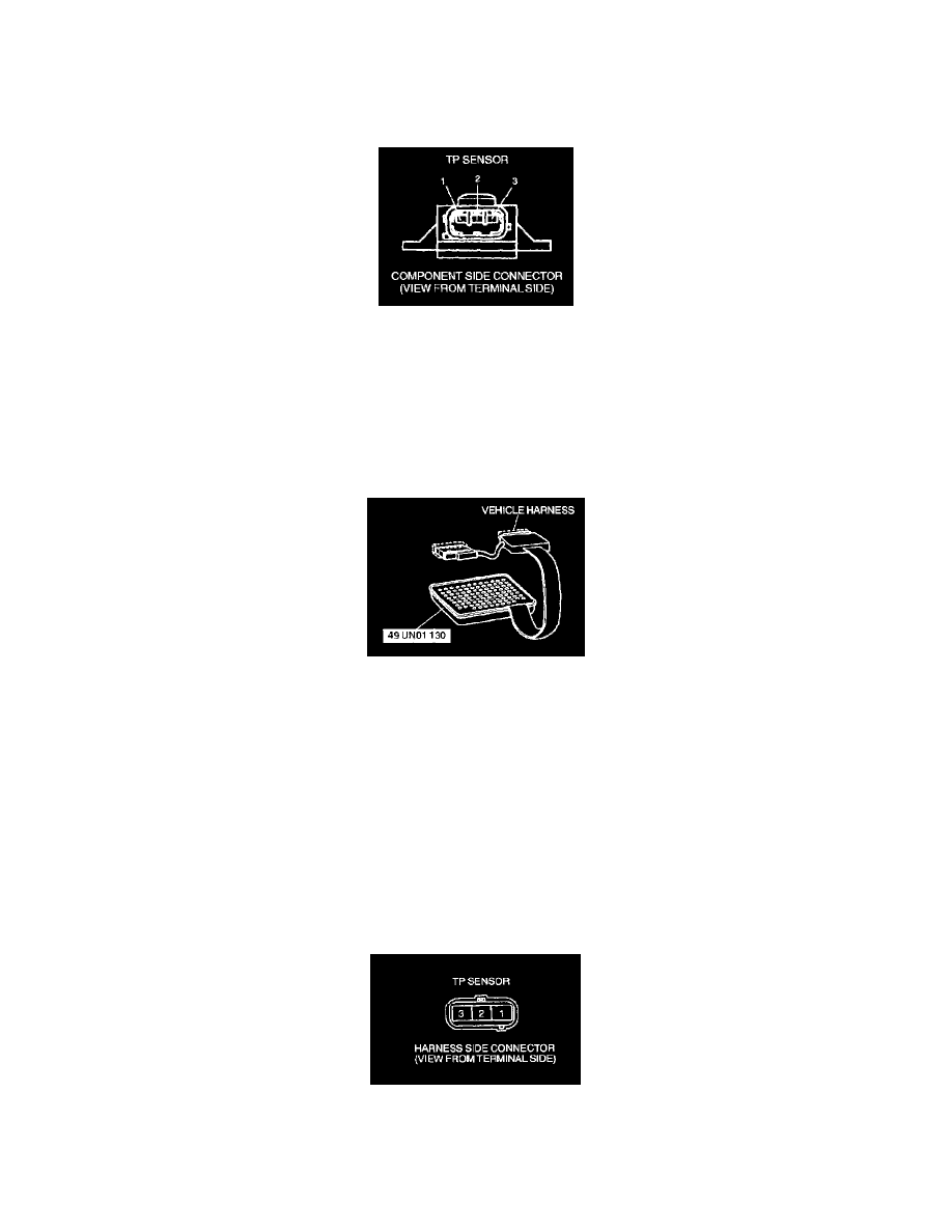
1. Disconnect TP sensor connector.
2. Measure the resistance between TP sensor terminals 1 and 3 using an ohmmeter
-
If not as specified, replace the TP sensor.
-
If as specified, but TP V PID value or PCM terminal 89 voltage is out of specification, perform the "Circuit Open/Short Inspection".
Specification
3.2 - 4.8 kOhms
Circuit Open/Short Inspection
1. Disconnect the PCM connector.
2. Connect the SST (104 Pin Breakout Box) with the PCM disconnected.
3. Tighten the connector attaching bolt.
Tightening torque
7.9 - 10.7 N.m {80 - 110 kgf.cm, 69.5 - 95.4 in.lbf}
4. Check the following wiring harness for open or short (Continuity check).
Open circuit
-
If there is no continuity, the circuit is open. Repair or replace the harness.
-
TP sensor terminal 1 (harness-side) and 104 pin breakout box terminal 90
-
TP sensor terminal 2 (harness-side) and 104 pin breakout box terminal 89
-
TP sensor terminal 3 (harness-side) and 104 pin breakout box terminal 91
Short circuit
-
If there is continuity, the circuit is shorted. Repair or replace the harness.
-
TP sensor terminal 1 (harness-side) and power supply
-
TP sensor terminal 1 (harness-side) and body ground
-
TP sensor terminal 2 (harness-side) and power supply
-
TP sensor terminal 2 (harness-side) and body ground