
MPV LX V6-2.5L DOHC (2000)
Engine Control Module: Component Tests and General Diagnostics
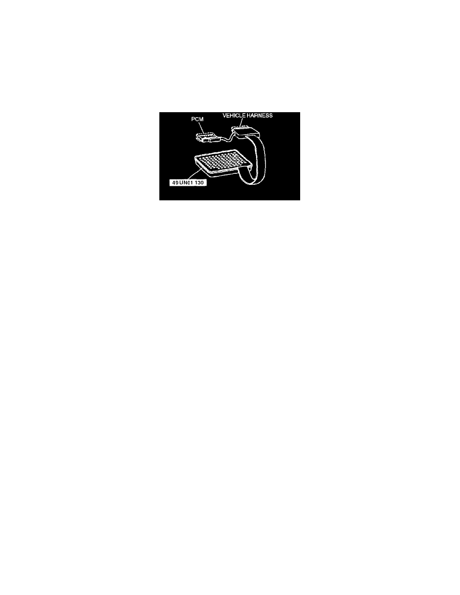
Using SST (104 Pin Breakout Box)
CAUTION: The PCM terminal voltages vary with measuring conditions and vehicle conditions. Always carry out a total inspection of the input
systems, output Systems, and PCM to determine the cause of trouble. Otherwise, a wrong diagnosis may be made.
PCM Inspection Using the SST (104 Pin Breakout Box)
1. Disconnect the negative battery cable.
2. Disconnect the PCM connector.
3. Connect the SST (104 Pin Breakout Box) to the PCM as shown.
4. Tighten the connector attaching bolt.
Tightening torque
7.9 - 10.7 N.m {80 - 110 kgf.cm, 69.5 - 95.4 in.lbf}
5. Connect the negative battery cable.
6. Measure the voltage at each terminal.
-
If an incorrect voltage is detected, inspect the related Systems, wiring harnesses and connectors referring to the Action column in the terminal
voltage table.