
MX-3 L4-1597cc 1.6L (1992)
Igniter: Description and Operation
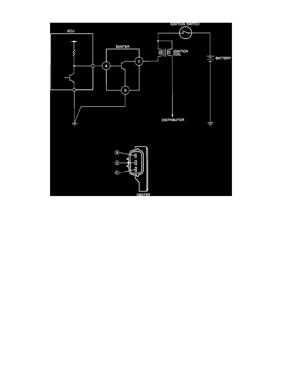
Igniter Circuit Diagram
PURPOSE
Igniter is an ECU controlled a switching device that activates the primary ignition coil circuit.
LOCATION
Near coil on left side of engine compartment.
OPERATION
The ECU determines optimum ignition timing from various inputs and transmits a primary current OFF signal to the igniter to control ignition
timing. The ECU calculates input from these devices to control ignition timing: ignition switch (START position), inhibitor switch (A/T), clutch
and neutral switches (M/T), throttle sensor, air flow meter, water thermosensor, crank angle sensor, and diagnosis connector (TEN terminal for
base timing adjustment).