
MX-5 Miata L4-1.8L DOHC (1996)
-
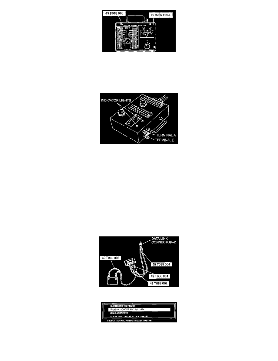
Connect the SSTs (Engine Signal Monitor and Harness adapter, power) to the SST (Harness Adapter). Use connector A of the harness adapter for
ECM terminals 1A through 1V and 3A through 3P. Use connector B for ECM terminals 4A through 4Z.
-
Place the SST (Sheet) on the SST (Engine Signal Monitor).
-
Measure the voltage at each ECM terminal by switching the selector switch and the monitor switch.
-
If any incorrect voltage is detected, check related systems, wiring harnesses and connectors referring to the possible malfunction in the terminal
voltage list.
CAUTION
-
Disconnecting the connectors of the ECM and the SST (Harness Adapter) while the battery is connected can damage the ECM and the SST
(Engine Signal Monitor). Disconnect the negative battery cable and the SST (Harness adapter, power) before disconnecting the connectors.
-
Applying voltage to terminals A and B of the SST can damage the tester.
NOTE:
-
The indicator lights of the SST (Engine Signal Monitor), provided for confirmation of the voltmeter range, is also used for detection of the
pulse such as the fuel injector control signal, which is difficult to detect by using the voltmeter.
-
Terminals A and B of the SST (Engine Signal Monitor) are for connection of an external instrument. By connecting an external instrument
such as a circuit tester or an oscilloscope, various inspections in addition to the measurement of the ECM terminal voltages are made possible.
-
If the tires are rotated by using a chassis roller with the ignition switch at ON, the ABS control module may memorize the action as a
malfunction and the ABS warning light may illuminate. (Refer to the Troubleshooting Notes for the antilock brake system.) If the ignition
switch is turned to LOOK and then to ON again, the ABS warning light will not illuminate, because the action will be considered a past
malfunction.
USING THE SSTS (NGS)
-
In the passenger compartment, connect the SSTs (NGS) to the data link connector-2. Located under the driver side dashboard.
-
Referring to the NGS instruction manual, select the PID/DATA MONITOR AND RECORD function.
-
Referring to the 1996 Service Highlights, inspect each ECM input/output signal.
NOTE
-
The PID/DATA MONITOR AND RECORD function is to monitor the calculation value of input/output signals in the ECM. Deviation in the