
MX-5 Miata L4-1.8L DOHC (1996)
3. Remove components in numerical sequence shown in Fig. 8.
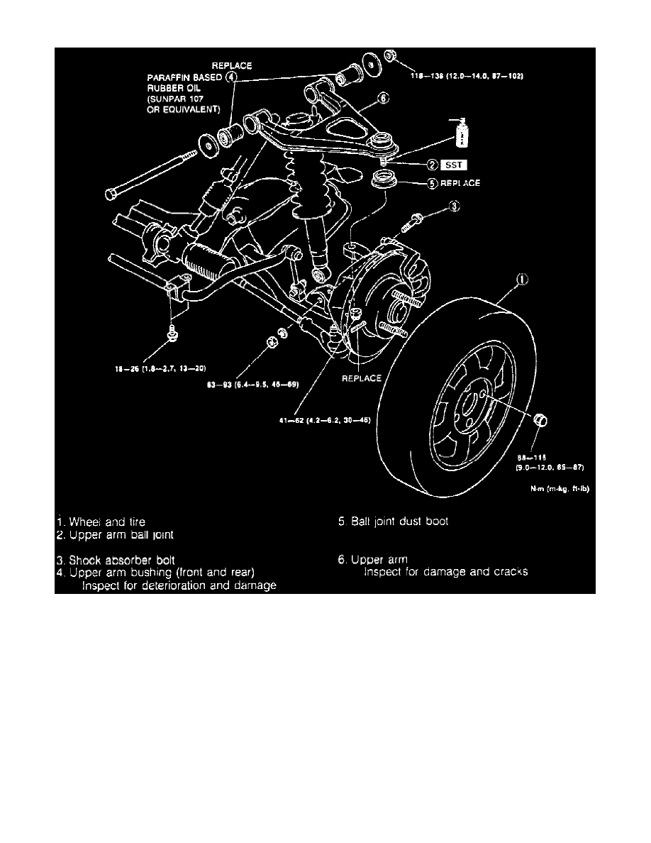
Fig. 4 Front Suspension Assembly
4. Reverse procedure to install, noting the following:
a. Using puller tool No. 490118850C, or equivalent, separate ball joint from knuckle.
b. When installing, loosely tighten upper arm, strut, and stabilizer control link bolts, then lower vehicle and tighten lower arm, strut and stabilizer
control links to specification.