
MX-5 Miata L4-1597cc 1.6L DOHC (1992)
Hydraulic Control Assembly - Antilock Brakes: Testing and Inspection
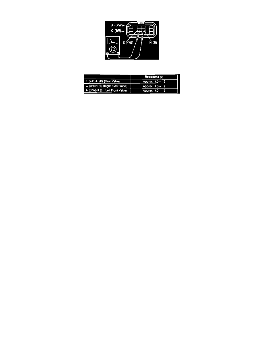
Fig. 34 Valve Connector Pin Identification
Fig. 35 Valve Resistance Specifications
1.
Disconnect hydraulic unit 12 pin connector.
2.
Using ohmmeter, check for resistance of terminals shown in Figs. 34 and 35.
3.
If resistance is not as specified, replace hydraulic unit.
4.
If resistance is as specified, check wiring harness from hydraulic unit to ABS control unit.