
MX-5 Miata L4-1597cc 1.6L DOHC (1992)
Igniter: Description and Operation
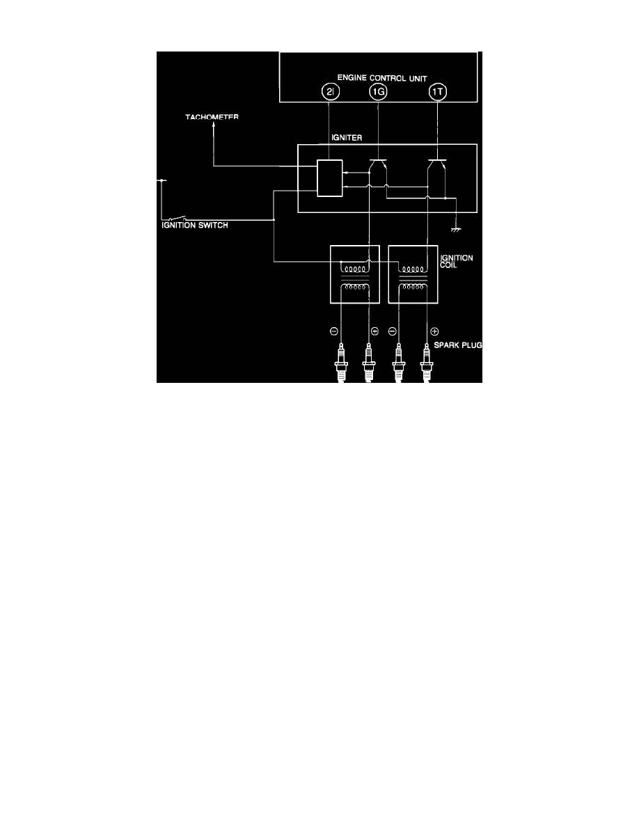
Ignition System Circuit Diagram
This vehicle is equipped with a distributorless ignition system. The Igniter, located on the right side inner fender, is a switching device that activates the
primary ignition coil circuit. The ECU determines optimum ignition timing from various inputs and transmits a primary current "OFF" signal to the
igniter to control ignition timing.
The ECU calculates input from these devices to control ignition timing:
^ Crank angle sensor "Ne" signal
^ Crank angle sensor "G" signal
^ Ignition switch ("START" position)
^ Water thermosensor
^ Airflow meter
^ Throttle sensor
^ Neutral and clutch switches
^ Diagnosis connector (for base timing adjustment)