
MX-5 Miata L4-2.0L (2008)
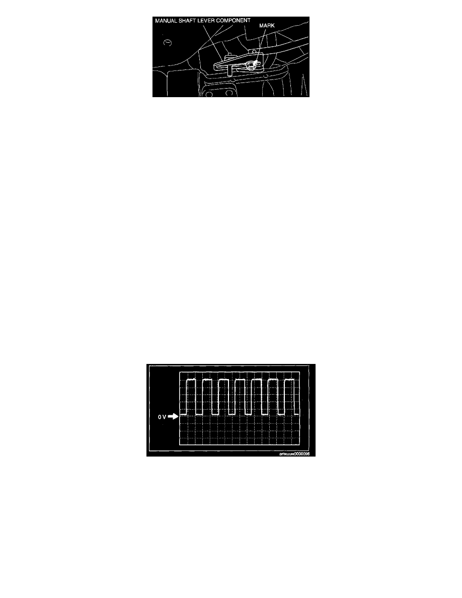
11. Align the mark of the manual shaft lever component as shown in the figure.
12. Install the manual shaft lever component installation nut.
Tightening torque 10.8 - 14.7 Nm (111 - 149 kegs-cm, 96.4 - 129.3 inch lbs.)
13. Install the insulator.
Tightening torque 8 - 11 Nm (82 - 112 kegs-cm, 72 - 97 inch lbs.)
14. Install the middle pipe.
15. Install the tunnel member component,
16. Connect the negative battery cable.
17. Install the battery cover.
[M15M-D] Manual Transmission
VEHICLE SPEED SENSOR (VSS) INSPECTION [M15M-D]
Visual Inspection
1. Remove the VSS.
2. Verify that the sensor is free of any metallic shavings or particles.
^
If there is any malfunction, clean them off.
3. Install the VSS.
Wave Profile Inspection
1. Remove the PCM.
2. Connect M-MDS to DLC-2.
3. Connect oscilloscope test leads to the following PCM connector terminals.
^
(+) lead: PCM terminal 20
^
(-) lead: Negative battery terminal (-)
4. Start the engine.
5. Monitor VSS PID.
6. Inspect wave profile.
^
Oscilloscope setting: 1 V/DIV (Y), 10 ms/DIV (X), DC range
^
Vehicle condition: drive the vehicle at 10 km/h (6.2 mph)
-
If there is any malfunction, perform the "Open Circuit Inspection" or "Short Circuit Inspection".
Power Supply Voltage Inspection
1. Disconnect the VSS connector.
2. Turn the ignition switch to the ON position.