
MX-5 Miata L4-2.0L (2008)
Vehicle Speed Sensor: Component Tests and General Diagnostics
Vehicle Speed Sensor (VSS) Inspection [M15M-D, 5 spd.]
VEHICLE SPEED SENSOR (VSS) INSPECTION [M15M-D, 5 spd.]
Visual Inspection
1. Remove the VSS.
2. Verify that the sensor is free of any metallic shavings or particles.
^
If there is any malfunction, clean them off.
3. Install the VSS.
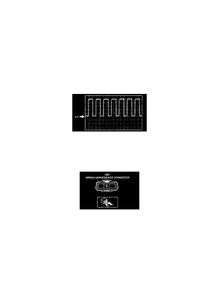
Wave Profile Inspection
1. Remove the PCM.
2. Connect WAS or equivalent to DLC-2,
3. Connect oscilloscope test leads to the following PCM connector terminals.
(+) lead: PCM terminal 20
(-) lead: Negative battery terminal
4. Start the engine.
5. Monitor VSS PID.
6. Inspect wave profile.
^
Oscilloscope setting: 1 V/DIV (Y), 10 ms/DIV (X), DC range
^
Vehicle condition: drive the vehicle at 10 km/ha (6.2 mph)
-
If there is any malfunction, perform the Open Circuit Inspection or Short Circuit Inspection.
Power Supply Voltage Inspection
1. Disconnect the VSS connector.
2. Turn the ignition switch to the ON position.
3. Measure voltage at VSS terminal B.
Vehicle speed sensor (VSS) voltage 4.5 - 5.5 V
^
If voltage is normal, go to Open Circuit Inspection and Short Circuit Inspection.
^
If there is any malfunction, repair wiring harness between VSS and PCM.
Open Circuit Inspection
1. Inspect the following circuit for open.
^
Power circuit (VSS terminal A to main relay terminal D)
^
Ground circuit (VSS terminal C to GND)
^
If an open circuit or short circuit is found, repair the malfunctioning wiring harness.
^
If there are no open or short circuits, perform the sensor rotor inspection.
Short Circuit Inspection