
MX-5 Miata LS L4-1.8L DOHC (2001)
3. Attach a wire to the tester lead to avoid damaging the terminals then inspect voltage, resistance or continuity, referring to the table above.
*1: When an isolation plate is not inserted to the short bar, voltage is approximately 0.2 V.
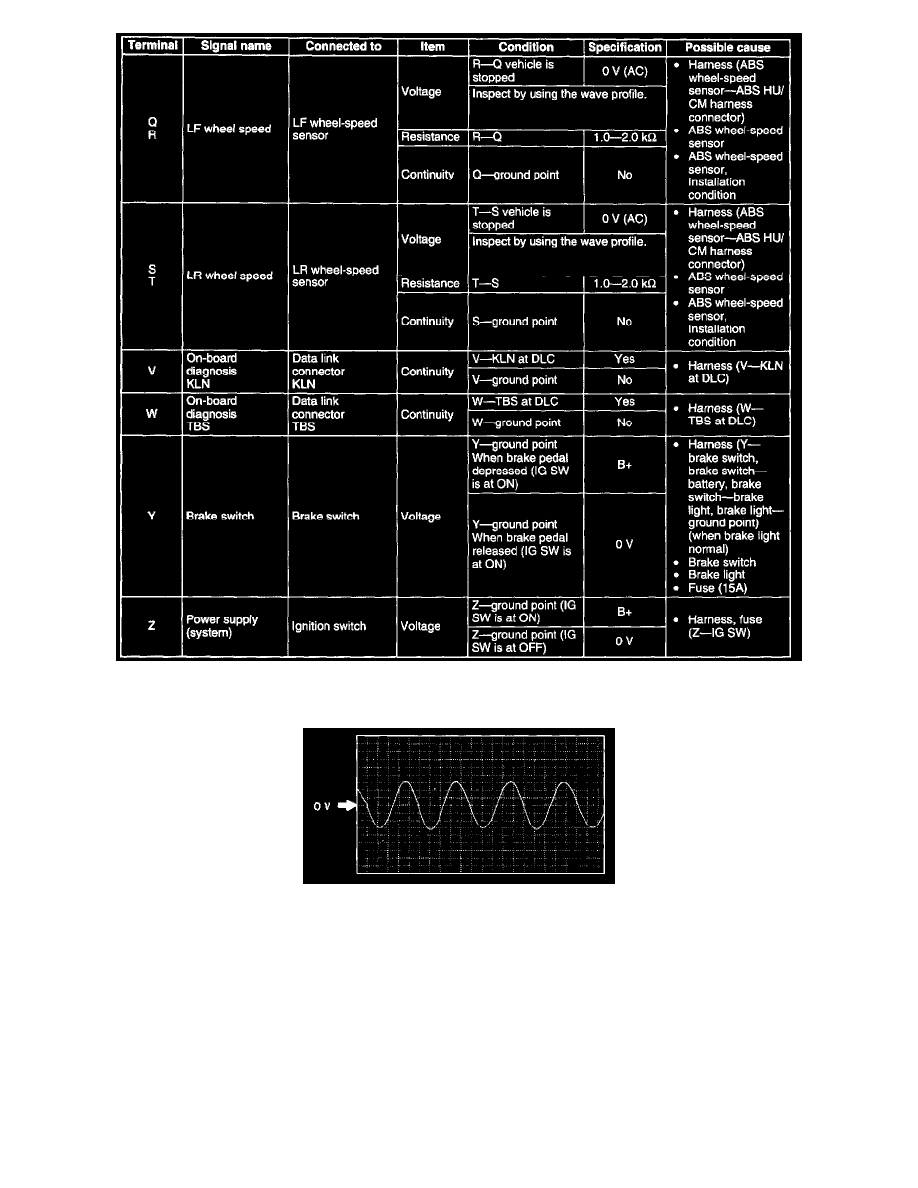
Inspection Using An Oscilloscope (Reference) Wheel speed
^
ABS MU/CM terminal:
RF: P (+)-O (-)
RR: N (+)-L (-)
LF: R (+)-Q (-)
LR: T (+)-S (-)
^
Oscilloscope setting: 0.2 V/DIV (Y), 4 ms/DIV (X), AC range
^
Vehicle condition: When turned 1 revolution per second
Note:
^
As vehicle speed increase, period of wave shorten.
^
If malfunctioning in the sensor rotor, wave profile warp.