
MX-5 Miata LS L4-1.8L DOHC (2001)
Hydraulic Control Assembly - Antilock Brakes: Testing and Inspection
SYSTEM INSPECTION
Preparation
1. Verify that the battery is fully charged. With the ignition switch on, verify that the ABS and BRAKE system warning lights goes out after 3
seconds.
2. If the lights stays on after 3 seconds, the ABS MU/CM detects a failure. Follow the troubleshooting procedures.
3. Turn the ignition switch off.
4. On level ground, jack up the vehicle and support it evenly on safety stands. Shift the transaxle to N position.
5. Release the parking brake.
6. Rotate the wheels by hand, and inspect for brake drag.
Using the SSTs
1. Perform the "Preparation."
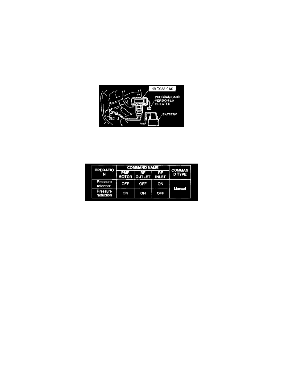
2. Connect the SSTs (NGS tester) to the data link connector-2 (DLC-2).
Note: Follow the order in the SST (NGS tester) instruction manual.
3. Set up an active command mode inspection according to the combination of commands below.
The chart above shows an example of a right wheel inspection.
Note: When working with two people, one should press on the brake pedal, the other should attempt to rotate the wheel being inspected.
4. Send the command while pressing on the brake pedal and attempting to rotate the wheel being inspected.
5. When pressure is being maintained, and click sound indicating the solenoid is operating comes from the ABS MU/CM, confirm that the wheel
does not rotate. When pressure is being reduced, and click sound indicating the solenoid is operating comes from the ABS MU/CM, confirm that
the wheel rotates, even though the brake pedal is being depressed.
Note:
^
To protect the ABS MU/CM, the solenoid valve used for simulations and the ABS motor stay on for 10 seconds each time they are switched
on.
^
Performing the inspections above determines the following.
-
The ABS MU/CM brake lines are normal.
-
The ABS MU/CM hydraulic system is not significantly abnormal.
-
The ABS MU/CM wiring is normal.
^
However, the following items cannot be checked. ABS MU/CM input system harness and parts
-
Extremely small leaks in the ABS MU/CM internal hydraulic system
-
Unusual intermittent occurrences in the above items
Without using the SSTs
1. Perform the "Preparation."
Caution: Connecting the wrong data link connector (DLC) terminal may possibly cause a malfunction. Carefully connect the specified terminal
only.