
MX-5 Miata Mazdaspeed L4-1.8L DOHC Turbo (2004)
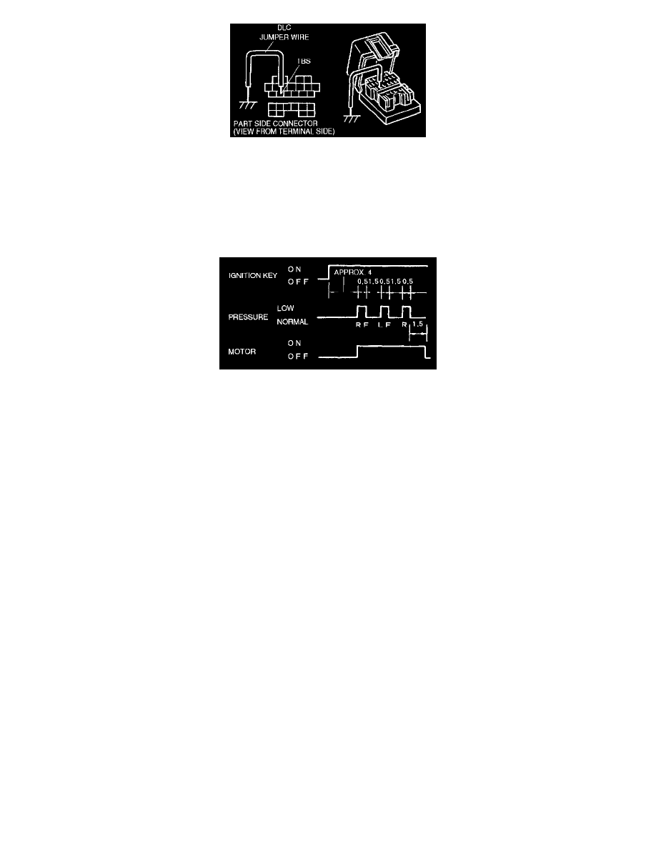
2. Use a jumper wire to short terminal TBS of the DLC to body GND.
Caution:
^
Connecting to the wrong data link connector (DLC) terminal may cause a malfunction. Carefully connect only to the specified terminal.
3. Depress the brake pedal, and have an assistant verify that the right front wheel does not turn.
4. With the brake pedal still depressed, turn the ignition switch on and verify that the brake is released momentarily (approx. 0.5 seconds) and that
the wheel turns when pressure reduction operates.
5. Inspect the operation of the remaining wheels in order: right front, left front, rear.
^
Replace the ABS HU/CM if wheels do not rotate.
^
Inspect brake piping to ABS HU/CM if operation of the remaining wheel order is not within specified.
Note
^
If Steps 4 and 5 show correct operation, the following systems are okay:
-
Brake piping to ABS HU/CM
-
Braking system, including ABS HU/CM
-
Electrical system in ABS HU/CM (solenoid, ABS motor, etc.)
^
The following are not inspected with above steps:
-
Input system and harness of ABS HU/CM
-
Intermittent failure
-
Fluid leakage from brake including the ABS HU/CM and master cylinder
6. Turn the ignition switch off and remove the jumper wire.