
MX-5 Miata Mazdaspeed L4-1.8L DOHC Turbo (2004)
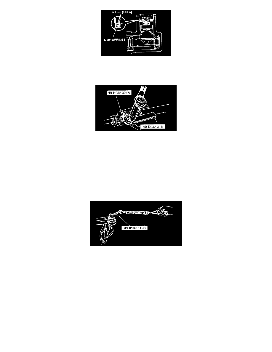
2. Install the roller component, needle roller, holder, dish springs, friction block, and the spring as shown.
3. Tighten the adjusting cover to 9.8 Nm (100 kgf-cm, 87 inch lbs.), then loosen it 25° - 45°. Use the SSTs to secure the adjusting cover and the
locknut.
Tightening torque 40 - 58 Nm (4.0 - 6.0 kgf-m, 29 - 43 ft. lbs.)
4. Measure the starting torque of the pinion using the SST.
^
If not as specified, repeat Steps 2 and 3.
Standard
Center of rack ±90° 1.0 - 1.1 Nm (10 - 12 kgf-cm, 8.7 - 10.4 inch lbs.)
Pull scale reading 10 - 11 N (1.0 - 1.2 kgf, 2.2 - 2.4 lbs.)
STEERING GEAR AND LINKAGE INSPECTION
Tie-rod End Inspection
1. Inspect the tie-rod end for damage and boot cracks. Replace it as necessary.
2. Inspect the ball joint for looseness. Replace the tie-rod end as necessary.
3. Rotate the ball joint 5 times.
4. Measure the rotation torque of the ball joint using the SST and pull scale.
^
If not as specified, replace the tie-rod end.
Rotation torque 0.1 - 3.1 Nm (1 - 32 kgf-cm, 0.9 - 27.7 inch lbs.)
Pull scale reading 0.5 - 15.4 N (0.05 - 1.58 kgf, 0.2 - 3.4 lbs.)
Tie Rod Inspection
1. Inspect the tie rod for bending and damage. Replace it as necessary.
2. Inspect the ball joint for looseness. Replace the tie rod as necessary.
3. Swing the tie rod 5 times.