
MX-6 L4-1991cc 2.0L DOHC (1993)
Alignment: Service and Repair
Rear Wheel Alignment
Preliminary Checks
1.
Ensure tire pressure is as specified by manufacturer.
2.
Inspect ball joints and steering linkage for excessive looseness, repair or replace as necessary.
3.
Ensure vehicle is level and has no luggage or passenger load.
4.
Ensure difference in height from center of wheel to fender brim between right and left sides is equal.
Camber
Camber is not adjustable and is set to specifications during production. Whenever camber is moved out of specified angle, check all parts of rear
suspension and body alignment. Repair of replace defective part(s) as required.
Toe-In
1. Raise and support vehicle, then remove wheel.
2. Remove crossmember cap, then disconnect stabilizer.
3. Remove lateral link outside bolt and nut.
4. Mark cam plate and crossmember, then remove nut, cam plate, adjusting bolt and rear lateral link.
5. Support crossmember with jack, then remove mounting bolts.
6. Remove front lateral link bolt and link.
7. Remove brake cable bracket, then trailing link.
8. Reverse procedure to install. Loosely tighten lateral and trailing link bolts and nuts, then lower vehicle and tighten to specifications.
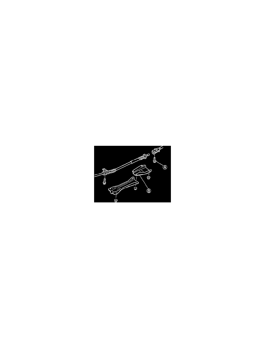
Turning Angle
Fig. 1 Removing Cover & Joint Bolt
1.
Raise and support vehicle.
2.
Remove cover B and joint bolt A, Fig. 1.
3.
Slide shaft out of joint.
4.
Remove plug from rear steering gear and, sighting through hole, turn steering angle input shaft to align notch in input shaft with center of hole.
5.
Remove set bolt attached to rear steering gear and install it in steering gear to set input shaft, torquing to 43-69 inch lbs. After input shaft is set,
manually turn rear joint and check that shaft does not move.
6.
Lower vehicle and check front and rear wheel alignment, adjusting as necessary.
7.
Mark steering straight ahead position as follows:
a. Place a piece of masking tape on steering wheel and column cover.
b. Drive vehicle on a straight, flat road for at least 18.6 ft. and note steering wheel position. Stop and mark straight ahead position on steering
wheel and column cover tape.
8.
Install shaft and rear joint removed in step 3, torquing bolt to 191-269 inch lbs.
9.
Install and tighten a new wire on joint boot.
10.
Install set bolt in rear steering gear, torquing to 14-21 ft. lbs.
11.
Check steering angle transfer shaft alignment as follows:
a. With marks between steering wheel and column cover aligned, check that rear wheels do not turn off center when engine is started.
b. If rear wheels move, repeat adjustment procedure.
Vehicle Ride Height
Measure vehicle ride height from center of the wheel to fender rim. Difference between left and right sides must not exceed 0.39 inch.