
MX-6 L4-1991cc 2.0L DOHC (1993)
Powertrain Control Module (PCM): Component Tests and General Diagnostics
INSPECTION
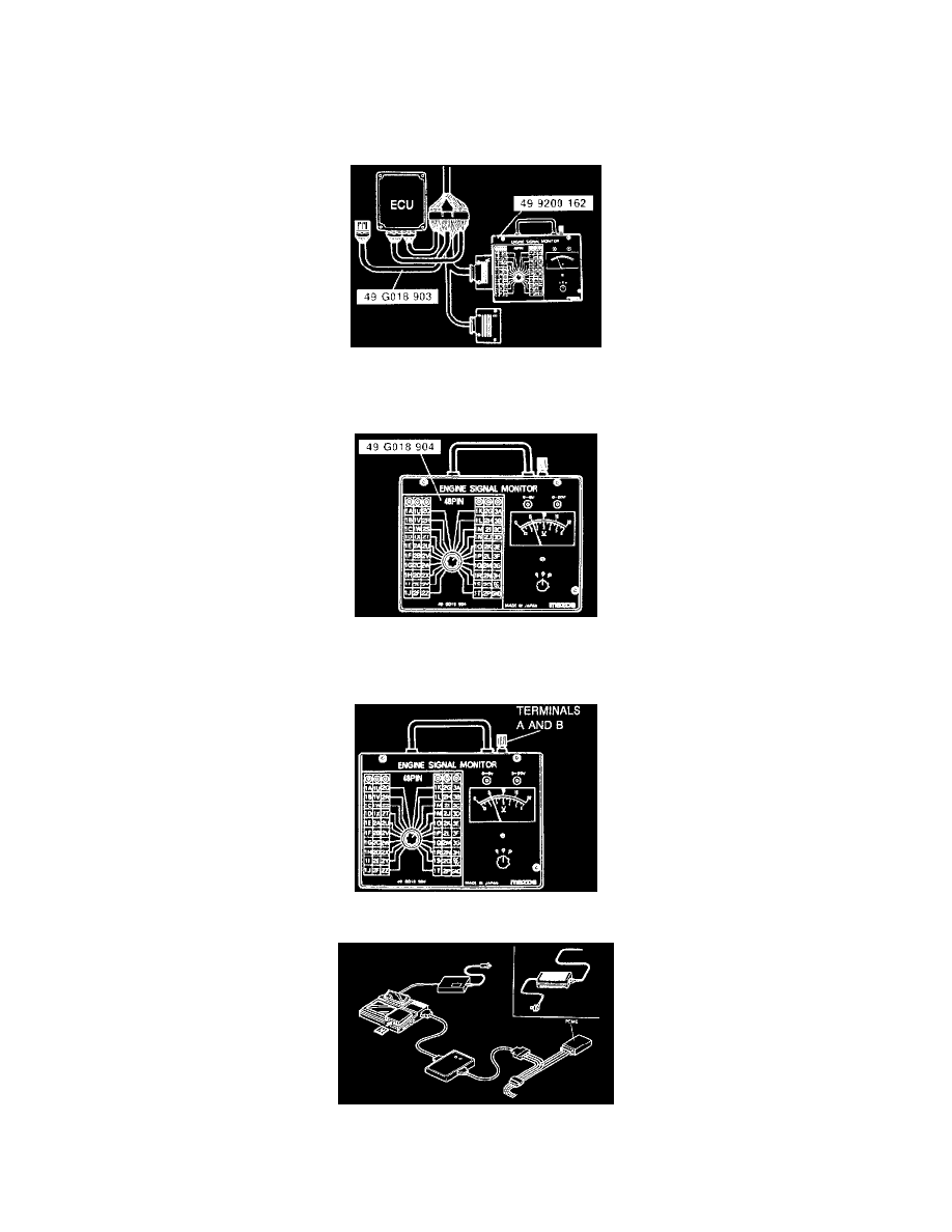
ENGINE SIGNAL MONITOR
1. Disconnect the Powertrain Control Module (PCME) connectors.
2. Connect the Special Service Tools (SSTs). (Engine Signal Monitor and Adapter) to the PCME as shown.
NOTE: Use connector B of Adapter from terminal 2A through 2P Automatic Transmission (ATX).
3. Place the SST (sheet) on the Engine Signal Monitor.
4. Measure the voltage at each terminal.
5. If any PCME terminal voltage is incorrect, check the related input or output devices and wiring. If no problem is found, replace the PCME.
CAUTION: NEVER APPLY VOLTAGE TO SST TERMINALS A AND B.
DT-S1000
1. Disconnect the PCME connector.
2. Assemble the DT-S1OOO.