
MX-6 L4-1991cc 2.0L DOHC (1993)
Alternator: Description and Operation
The electrical charging system is a negative ground system consisting of an integral alternator/voltage regulator (IAR), charge indicator, storage battery
and necessary wiring and cables.
With the ignition switch in the Run position, voltage is applied through the charge indicator lamp I circuit to the voltage regulator. This turns the
regulator on allowing current to flow from the battery sense A circuit to the alternator field coil. When the engine is started, the alternator begins to
generate alternating AC current which is converted to DC current by the rectifier assembly internal to the alternator. This current is then supplied to the
vehicle's electrical system through the output stud located on the rear of the alternator. Once the alternator begins generating current, a voltage signal is
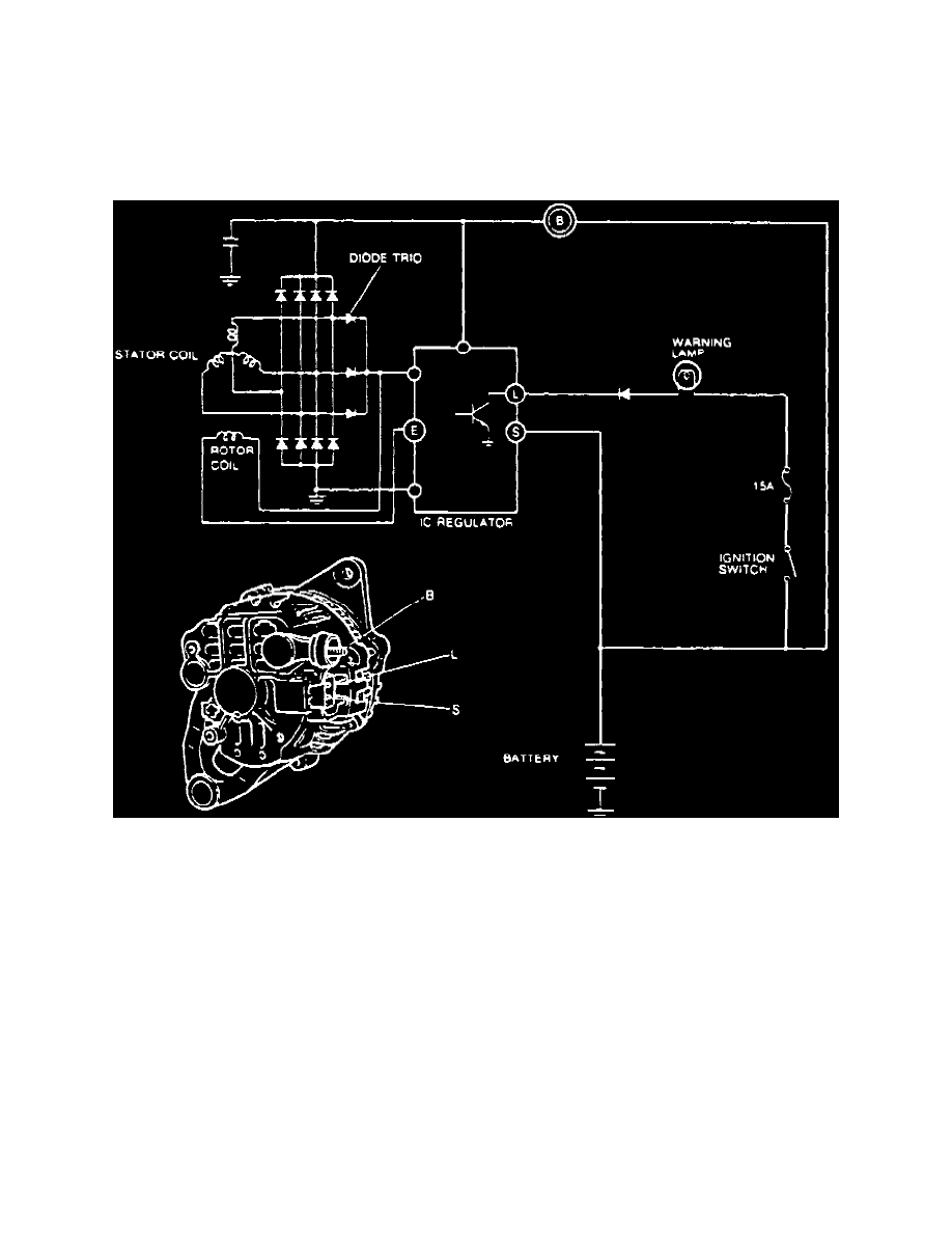
taken from the alternator stator and fed back to the regulator S circuit, turning off the charge indicator, Fig. 4.
Fig. 4 Alternator Charging System