
MX-6 LS V6-2.5L DOHC (1997)
Step 5
Set the turn switch to the left position and measure the voltage at terminal F (G/Y) of the flasher unit connector.
Ohmmeter Connection
Action Chart
Step 6
Set the turn switch to the right position and measure the voltage at terminal E (B/R) of the flasher unit connector.
Ohmmeter Connection
Action Chart
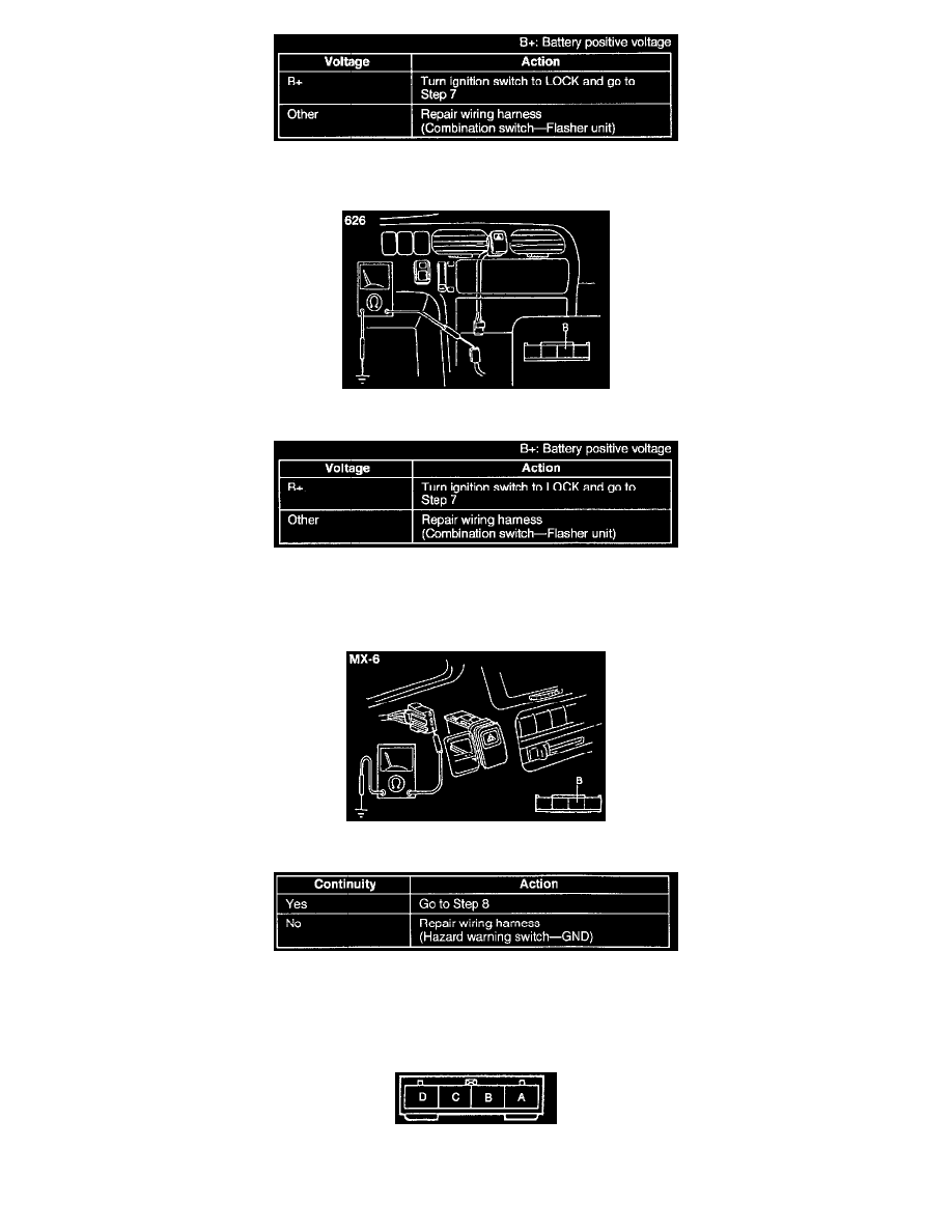
Step 7
1. Remove the hazard warning switch.
2. Check for continuity between terminal B (B) of the hazard warning switch connector and ground.
Terminal Identification