
Navajo 4WD V6-4.0L OHV (1991)
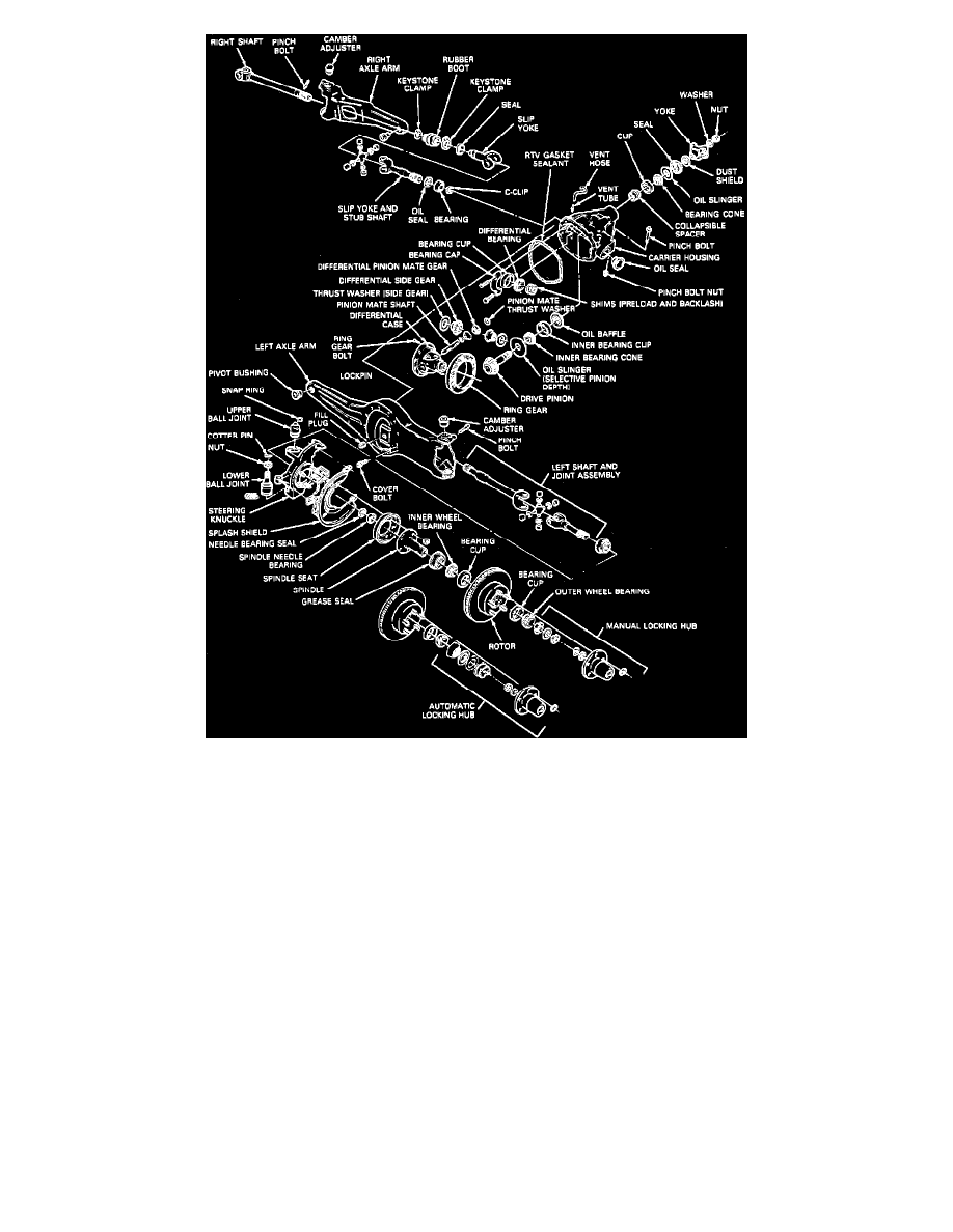
Fig. 1 Exploded View Of Front Axle Assembly
1.
Disconnect driveshaft from yoke. Position driveshaft aside so it will not interfere with carrier removal.
2.
Remove both spindles, Fig. 1, then the left and right shaft and U-joint assemblies as described previously.
3.
Support carrier using a suitable jack, then remove carrier to support arm attaching bolts.
4.
Remove carrier from support arm, then drain lubricant and remove carrier from vehicle.
5.
Install carrier in suitable holding fixture, then rotate slip yoke and shaft assembly until open end of snap ring is exposed.
6.
Remove snap ring, then the slip yoke and shaft assembly from carrier.
7.
Remove oil seal and caged needle bearings simultaneously from carrier using tools No. T50T-100-A and D880L-100-A or equivalent. Discard seal
and bearings.
8.
Reverse procedure to install. Note the following:
a. Clean mating surfaces of carrier and support arm. Apply a narrow bead of RTV sealant to mating surfaces.
b. Install carrier attaching bolts hand tight, then torque in a clockwise or counterclockwise pattern to 40-50 ft. lbs.
c. Torque carrier to axle arm shear bolt to 75-95 ft. lbs.
d. Torque driveshaft to yoke U-bolt nuts to 8-15 ft. lbs.
Spindle, Shaft & Joint Assembly