
Protege L4-1.5L DOHC (1995)
Powertrain Control Module (PCM): Testing and Inspection
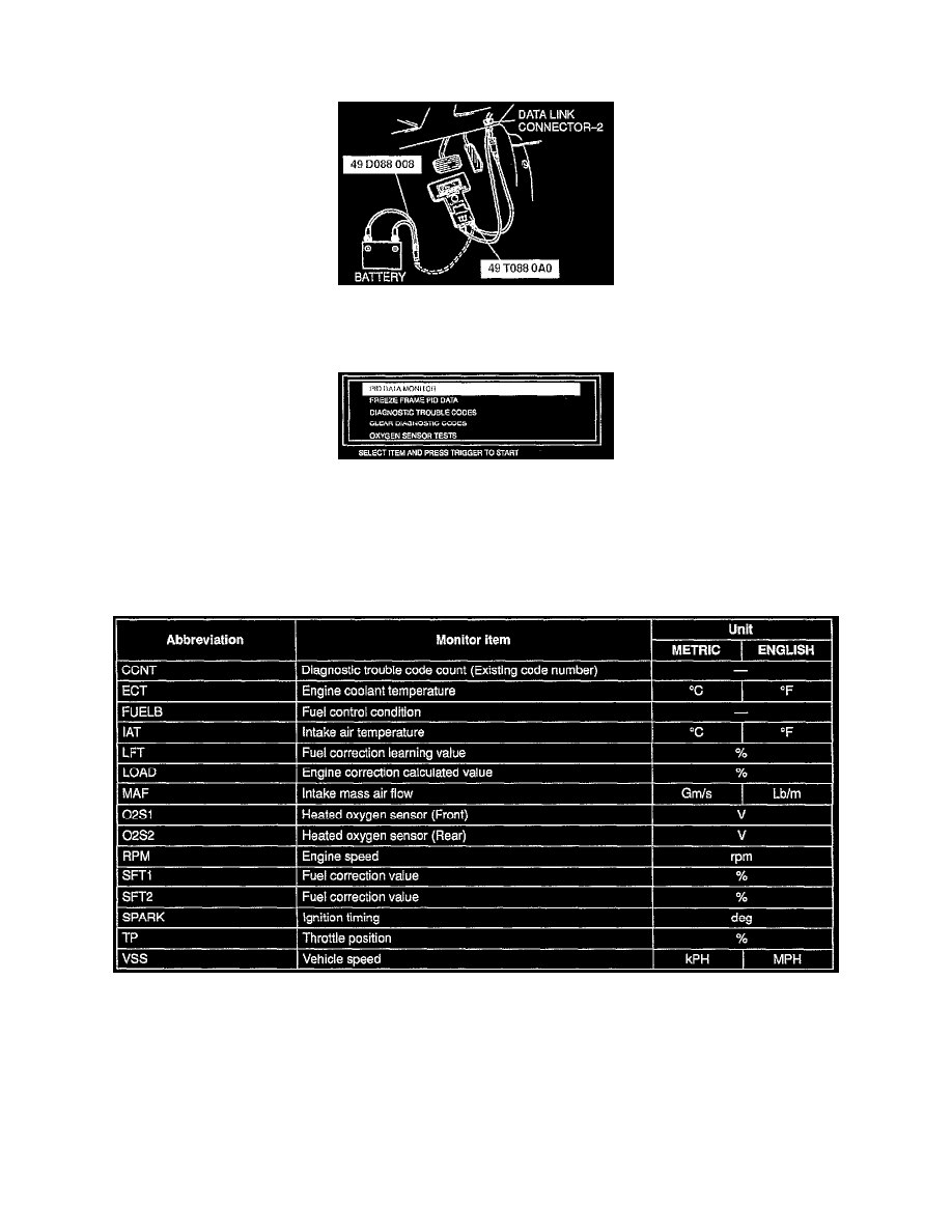
With NGS Connected at DLC
1. In the passenger compartment, connect the SST to the data link connector-2 as shown in the figure.
2. Referring to the NGS operational manual, select the PID DATA MONITOR function.
3. Referring to the following list, inspect each PCM input/output signal.
Note
^
The PID DATA MONITOR function is to monitor the calculation value of input/output signals in the PCM. Deviation in the value does not
always indicate malfunction in the related input/output devices (sensors and solenoids).
^
For inspection of the input/output signals other than listed below, check voltage at the applicable PCM terminal by using the SST (engine
signal monitor).
4. If normal output signal cannot be detected when all input signals are normal, replace the PCM.
Link monitor table
PID DATA MONITOR (GENERIC OBDII FUNCTIONS)
Note:
^
Each data is indicated in either English system or metric system.
The units can be switched by selecting "ENGLISH/METRIC UNIT SELECTION" on the tester screen. (Refer to the NGS operation manual.)