
Protege L4-2.0L DOHC (2003)
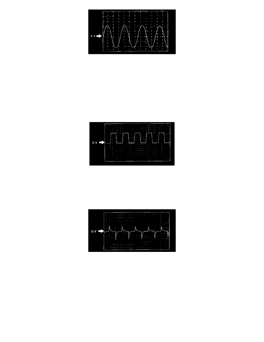
Wheel speed
^
ABS HU/CM terminal:
RR: A (+) - B (-)
LR: C (+) - F (-)
RF: D (+) - G (-)
EF: E (+) - I (-)
^
Oscilloscope setting: 1 V/DIV (Y), 2 ms/DIV (X), AC range
^
Vehicle condition: Driving 30 km/h (18.6 mph)
Note:
^
As vehicle speed increases, period of wave shortens.
^
If there is malfunctioning in the sensor rotor, wave profile warps.
Vehicle speed output (to PCM) (ATX only)
^
ABS HU/CM terminal: J (+) - AA (-)
^
Oscilloscope setting: 1 V/DIV (Y), 5 ms/DIV (X), DC range
^
Vehicle condition: Driving 30 km/h (18.6 mph)
Note:
^
As vehicle speed increases, period of wave shortens.
Vehicle speed output (to instrument cluster)
^
ABS HU/CM terminal: Q (+) - AA (-)
^
Oscilloscope setting: 1 V/DIV (Y), 5 ms/DIV (X), DC range
^
Vehicle condition: Driving 30 km/h (18.6 mph)
Note:
^
As vehicle speed increases, period of wave shortens.