
Protege DX L4-2.0L DOHC (2002)
Camshaft Position Sensor: Component Tests and General Diagnostics
Resistance Inspection
NOTE: Perform the following test only when directed.
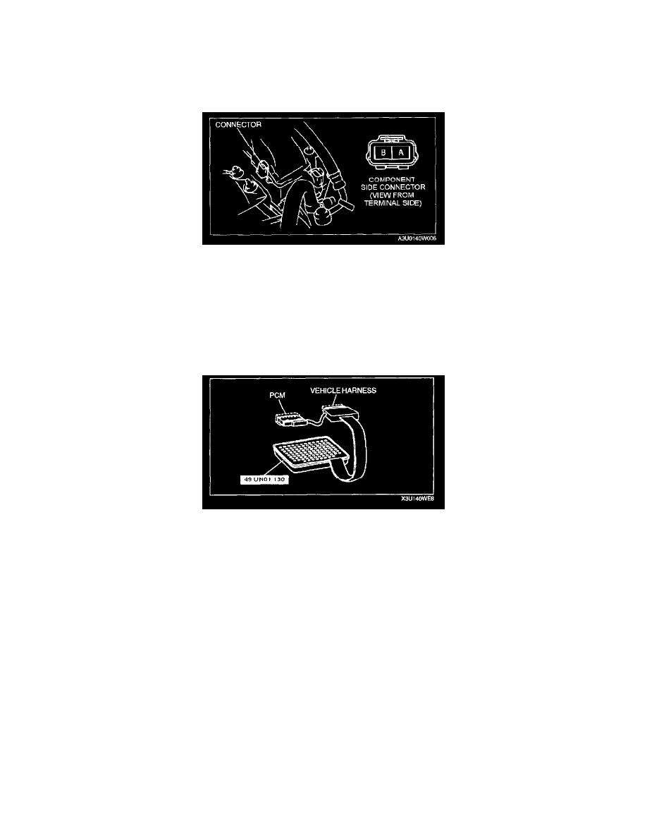
1. Disconnect the CMP sensor connector.
2. Measure the resistance between the CMP sensor connector terminals A and B using an ohmmeter.
-
If not as specified, replace the CMP sensor.
-
If CMP sensor resistance is okay, but PID value or PCM terminal 85 and 86 voltage are out of specification, carry out the Circuit Open/Short
Inspection".
Specification: 0.95 - 1.25 kOhms
Circuit Open/Short Inspection
1. Remove the PCM.
2. Connect the SST (104 Pin Breakout Box) to the PCM as shown.
3. Tighten the connector attaching screw.
Tightening torque
7.9 - 10.7 N.m {80 - 110 kgf.cm, 69.5 - 95.4 in.lbf}
4. Inspect for an open or short circuit in the following wiring harnesses by probing the applicable sensor and SST (104 Pin Breakout Box) terminals
with ohmmeter leads.
-
If there is an open or short circuit, repair or replace wiring harnesses.
-
If there is no open or short circuit, replace the CMP sensor.
Open circuit
-
CMP signal circuit (CMP sensor connector terminal A and PCM connector terminal 85)
-
CMP signal circuit (CMP sensor connector terminal B and PCM connector terminal 86)
Short circuit
-
CMP signal circuit (CMP sensor connector terminal A and PCM connector terminal 85 to GND)
-
CMP signal circuit (CMP sensor connector terminal B and PCM connector terminal 86 to GND)
5. Reconnect the CMP sensor connector.