
Protege DX L4-2.0L DOHC (2002)
Vehicle Speed Sensor: Component Tests and General Diagnostics
VEHICLE SPEEDOMETER SENSOR (VSS) INSPECTION [ATX]
Visual Inspection
1. Remove the VSS.
2. Make sure that the sensor is free of any metallic shavings or particles.
^
If any are found on the sensor, clean them off.
3. Install the VSS.
Wave profile Inspection
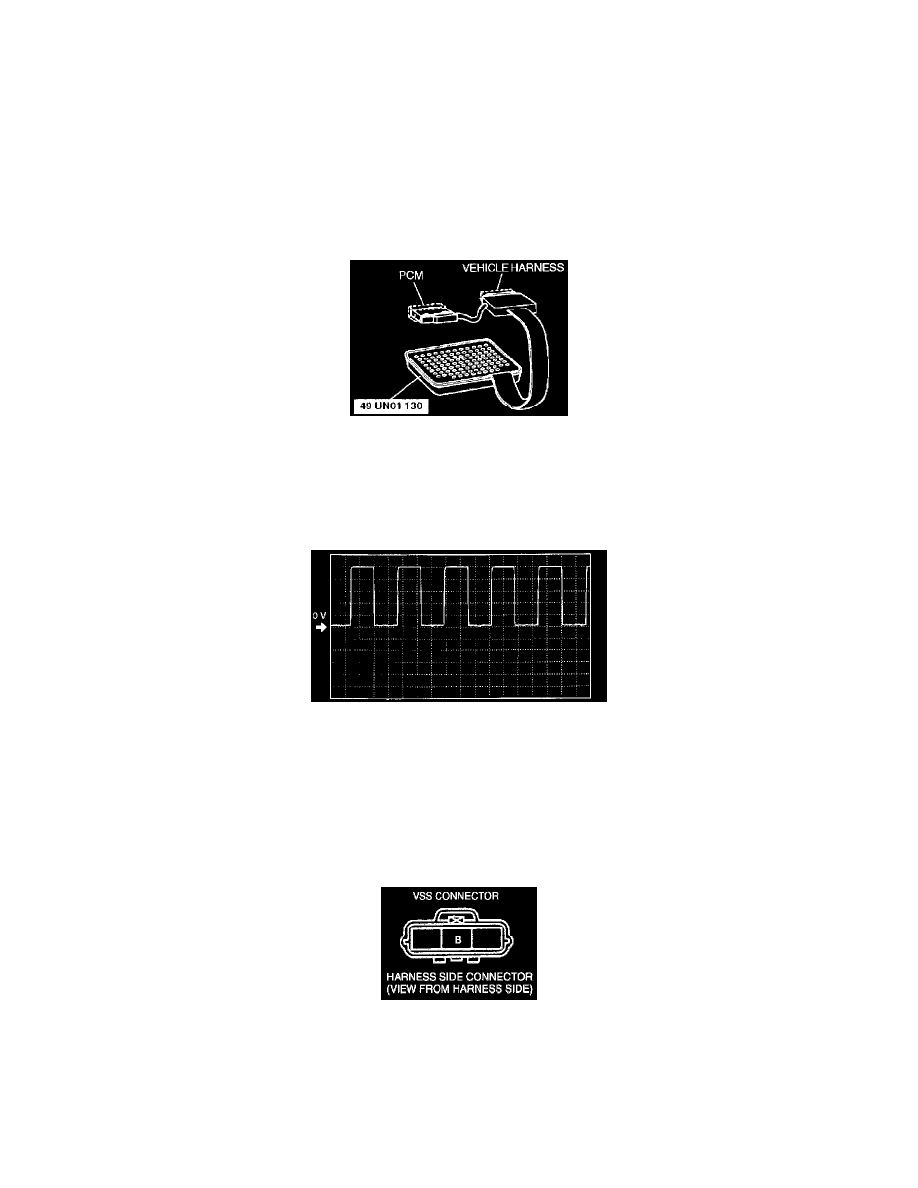
1. Remove the PCM.
2. Connect WDS or equivalent to DLC-2 connector.
3. Connect the SST (104 Pin Breakout Box) to the PCM as shown.
4. Connect oscilloscope test leads to the following PCM connector terminals.
^
(+) lead: PCM terminal 58
^
(-) lead: PCM terminal 103
5. Start the engine.
6. Monitor VSS PID.
7. Inspect wave profile.
^
PCM terminal: 58 (+) - 103 (-)
^
Oscilloscope setting: 1 V/DIV (Y), 2.5 ms/DIV(X), DC range
^
Vehicle condition: drive the vehicle with 32 km/h (20 mph)
-
If wave profile or voltage are out of specifications, carry out the "Open Circuit Inspection" or "Short Circuit Inspection"
Power Supply Voltage Inspection
1. Disconnect the VSS connector.
2. Turn the ignition switch to ON.
3. Measure voltage at VSS connector terminal B (wiring harness side).
Specification 4.5 - 5.5 V
^
If voltage is okay, go to "Open Circuit Inspection" and "Short Circuit Inspection".
^
If voltage is wrong, repair wiring harness between VSS and PCM.
Open Circuit Inspection
1. Inspect the following circuit for open.