
Protege DX L4-2.0L DOHC (2002)
EGR Boost Sensor: Testing and Inspection
NOTE:
-
Perform the following test only when directed.
-
The following vacuum values are indicated by relative pressure from barometric pressure.
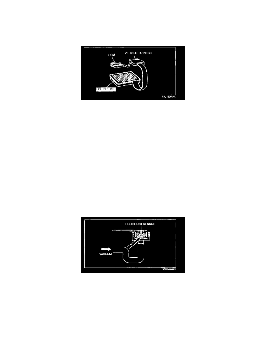
1. Remove the PCM.
2. Connect the SST (104 Pin Breakout Box) to the PCM as shown.
3. Tighten the connector bolt.
Tightening torque
7.9 - 10.7 N.m {80 - 110 kgf.cm, 69.5 - 95.4 in.lbf}
CAUTION: Do not apply a vacuum outside the specified limits. Doing so will damage the EGR boost sensor.
4. Turn the ignition switch to ON.
5. Disconnect the vacuum hose between the EGR boost sensor and intake manifold.
NOTE: The output voltage varies with the measuring condition.
6. Verify that the PCM 34 terminal voltage is within specification.
Measuring condition:
Input voltage: 4.5 - 5.5 V
Outside temperature: 10 - 50 °C {50 - 122 °F}
Sea level: -20 - 3,000 m {-656 - 9,840 ft}
Specification
Measuring voltage: 2.3 - 4.7 V
7. Apply vacuum of -26.6 kPa {-200 mmHg, -7.85 inHg} to EGR boost sensor and verify that PCM 34 terminal voltage change from Step 6 is
within specification.
-
If not as specified, replace the EGR boost sensor.
-
If EGR boost sensor is okay, but PCM terminal 34 voltage is out of specification, carry out the "Circuit Open/Short Inspection".
Specification
Monitoring voltage variation: 0.8 - 1.3 V
Circuit Open/Short Inspection
1. Remove the PCM.