
Protege LX L4-1.6L DOHC (2000)
Note The component parts of the Special Service Tool (SST) (49 B017 001 or 49 G019 003) can be used as a suitable washer.
2. After tightening all the hub nuts to the same torque, put the dial gauge on the friction surface of disc plate 10 mm (0.39 inch) from the disc plate
edge.
3. Rotate the disc plate one time and measure the runout.
Runout limit
0.05 mm (0.002 inch)
Thickness Variation Inspection
1. Clean the disc plate-to-pad friction surface using a brake cleaner.
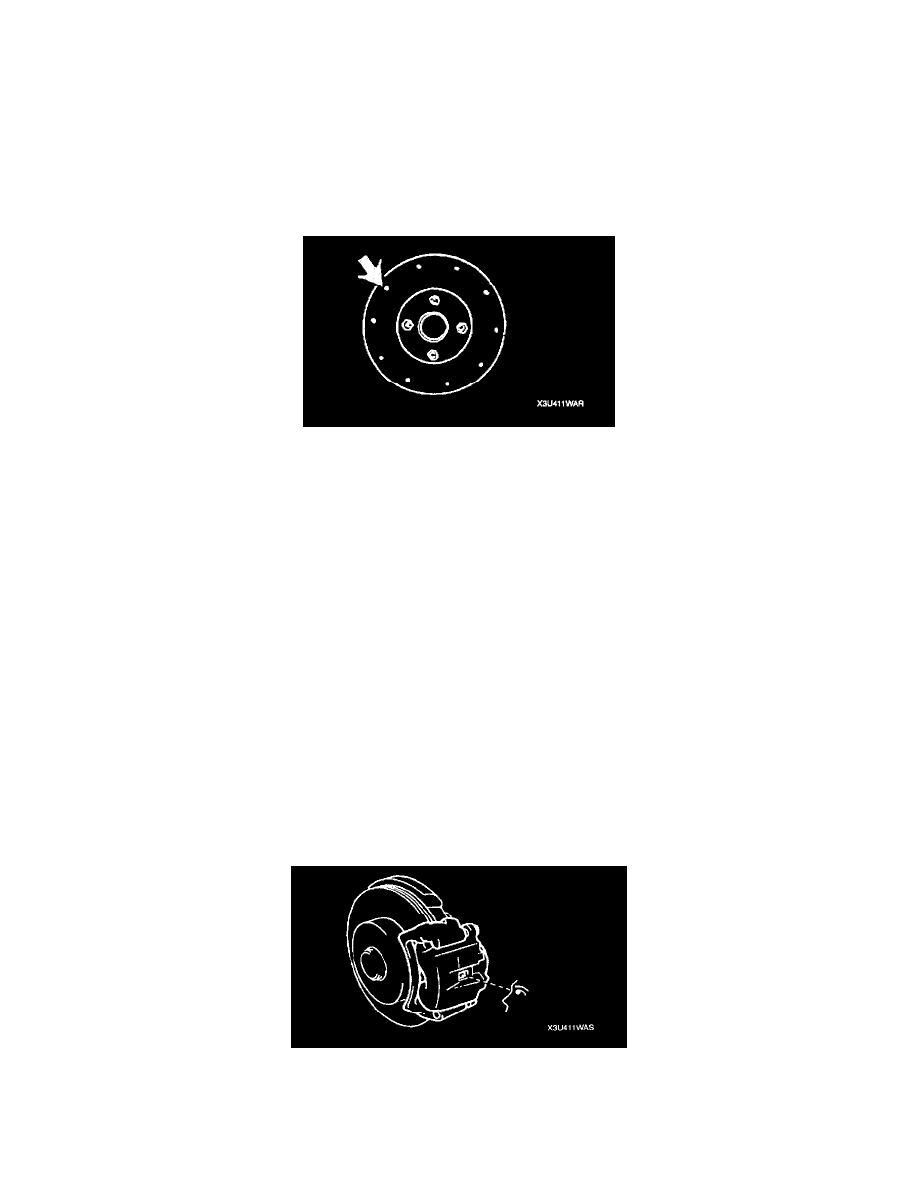
2. Measure the points indicated in the illustration using a caliper (micrometer).
3. Subtract the minimum value from the maximum, and if the result is not within specification, machine the disc plate using a lathe.
Thickness variation limit
0.015 mm (0.0005 inch)
Warning Do not exceed minimum disc plate thickness.
Disc Plate Thickness Inspection
Caution Excessive runout may result if the disc plate is removed from the vehicle then machined. Machine the disc plate while installed on the
vehicle.
1. Measure the thickness of the disc plate.
^
If the thickness is not within the specification, replace the disc plate.
Minimum
ZM: 20 mm (0.78 inch)
FP: 22 mm (0.87 inch)
Minimum thickness after machining using a brake lathe on-vehicle
ZM: 20.8 mm (0.82 inch)
FP: 22.8 mm (0.90 inch)
Disc Pad Thickness Inspection
1. Jack up the front of the vehicle and support it with safety stands.
2. Remove the wheels.
3. Verify the remaining thickness of the pads.
Thickness
ZM: 1.5 mm (0.059 inch) min.
FP: 2.0 mm (0.079 inch) min.
4. Replace the pads as a set: right and left wheels, if either one is at or less than the minimum thickness.