
Protege LX L4-1489cc 1.5L DOHC MFI (1998)
Fuel Gauge Sender: Testing and Inspection
Sensor Signal Test
SENSOR SIGNAL INSPECTION PROCEDURES
1. Find an unusual signal (Refer to procedures below).
2. Locate its source (Refer to procedures below).
3. Repair or replace the defective part.
4. Confirm that the unusual signal has been erased.
While referring to the diagnostic trouble code inspection section of the on-board diagnostic system, use the PID monitor to check the input signal
system relating to the problem.
1. Turn the ignition ON and idle the vehicle. You can assume that any signals that are out of specifications by a wide margin are unusual.
2. When recreating the problem, any sudden change in monitor input signals that is not consciously created by the driver can be judged as
unusual.
CAUTION:
-
Compare the NGS monitor voltage with the measurement voltage using the NGS "DIGITAL MEASUREMENT SYSTEM" function. If you use
another tester, misreading may occur.
-
When measuring voltage, attach the tester ground to the GND of the PCM that is being tested, or to the engine itself. If this is not done, the
measured voltage and actual voltage may differ.
-
After connecting the pin to a waterproof coupler, confirming continuity and measuring the voltage, check the waterproof connector for cracks. If
there are any, use sealant to fix them. Failure to do this may result in deterioration of the harness or terminal from water damage, leading to
problems with the vehicle.
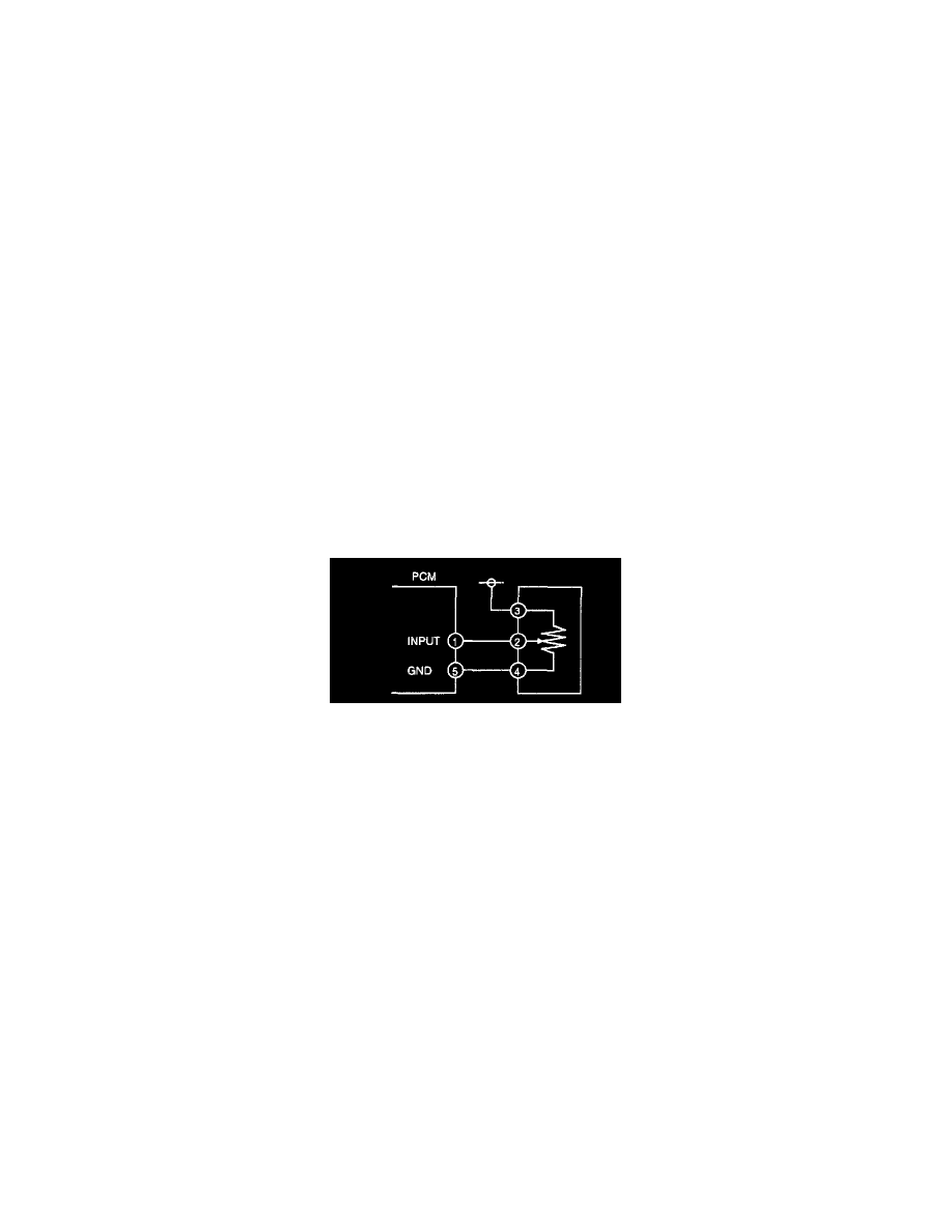
VARIABLE RESISTANCE TYPE 2 (FUEL TANK LEVEL AND MASS AIRFLOW SENSORS)
Investigate the input signal system
1. When you get an unusual signal, measure the #1 PCM terminal voltage.
(1) If the #1 terminal voltage and the NGS monitor voltage are the same, proceed to the next step.
(2) If there is a difference of 0.5 V or more, check the following points concerning the PCM connector:
-
Female terminal opening loose
-
Coupler (pin holder) damage
-
Pin discoloration (blackness)
-
Harness/pin clamp is loose or disconnected
2. When you get an unusual signal, measure the #2 sensor terminal voltage.
(1) If there is a 0.5 V or more difference between the sensor and NGS voltages, check the harness for open or short circuits.
(2) If the sensor and NGS voltages are the same, check the following points concerning the sensor connector. If there are no problems, proceed to
next investigation below.
-
Female terminal opening loose
-
Coupler (pin holder) damage
-
Pin discoloration (blackness)
-
Harness/pin clamp is loose or disconnected.
Investigate the electrical supply system
1. Confirm that the sensor #3 terminal is B+.
(1) If the measured voltage on the #3 terminal is B+, check the following points on the sensor connector. If there is no problem, proceed to next
investigation below.
-
Female terminal opening loose
-
Coupler (pin holder) damage
-
Pin discoloration (blackness)
(2) If the #3 terminal measures other than B+,
check the following points: