
Protege LX L4-1489cc 1.5L DOHC MFI (1998)
Fuel Tank Pressure Sensor: Testing and Inspection
Sensor Inspection
FUEL TANK PRESSURE SENSOR INSPECTION
NOTE: The following vacuum and pressure values are indicated by relative pressure from atmospheric pressure.
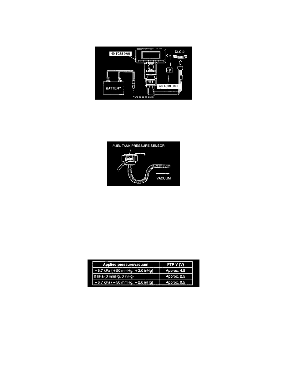
1. Connect the SSTs (NGS tester) to the data link connector-2.
2. Select the "PID/DATA MONITOR AND RECORD" function on the NGS display.
3. Select "FTP V" on the NGS display and press START. The NGS measure and shows the voltage.
4. Turn the ignition switch to ON.
CAUTION: Do not apply a vacuum or pressure outside of the specified limits. Doing so will damage the fuel tank pressure sensor.
5. Apply pressure then vacuum to the fuel tank pressure sensor according to the following procedure.
6. Decrease the application pressure from +6.7 kPa (+50 mmHg, +2.0 inHg) to -6.7 kPa (-50 mmHg, -2.0 inHg) and verify that the voltage at FTP
V decreases accordingly.
Reference data
NOTE: The output voltage varies with the measuring condition.
Measuring condition
-
Input voltage - 5 V
-
Outside temperature -25°C (77°F)
-
Atmospheric pressure -101.3 kPa (760 mmHg, 29.9 inHg)
Specification
7. If not as specified, perform the following inspection.
(1) Harness continuity
-
Between PCM terminal 4E and fuel tank pressure sensor terminal A
-
Between PCM terminal 3K and fuel tank pressure sensor terminal B
-
Between PCM terminal 31 and fuel tank pressure sensor terminal C