
RX7 2RTR-1308cc 1.3L MFI (1991)
Transmission Position Switch/Sensor: Description and Operation
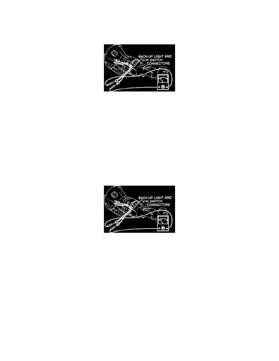
Back-Up Light and 5TH Switch (M/T)
Non-Turbo
Back-Up Light And 5th Switch
The Back-Up Light and 5th Switch is mounted on the transmission and wired to perform two functions. When reverse gear is engaged, the switch
completes the circuit to turn the back-up lights "ON." When 5th gear is engaged, a signal is sent to the ECU that is factored into calculations for outputs
such as fuel injection quantity, ignition timing and secondary air injection.
This switch directly affects ECU control of the air injection system split air solenoid valve. When the vehicle is operating in 5th gear, the solenoid valve
is energized, directing secondary air from the air control valve to the rear catalytic converter under specified driving conditions (refer to
RELATIONSHIP CHARTS in this section).
Back-up light/5th switch input voltage can be checked at ECU terminal 1T, ignition switch "ON." In 5th gear, terminal voltage should be below 2.0V.
In 1st through 4th gears, voltage should be approximately 12V.
For further information on the secondary air injection system, refer to EMISSION CONTROLS.
Turbo
Back-Up Light And 5th Switch
The Back-Up Light and 5th Switch is mounted on the transmission and wired to perform two functions. When reverse gear is engaged, the switch
completes the circuit to turn the back-up lights "ON." When 5th gear is engaged, a signal is sent to the ECU that is factored into calculations for outputs
such as fuel injection quantity, ignition timing and secondary air injection.
This switch directly affects ECU control of the air injection system split air solenoid valve. When the vehicle is operating in 5th gear, the solenoid valve
is energized, directing secondary air from the air control valve to the rear catalytic converter under specified driving conditions (refer to
RELATIONSHIP CHARTS in this section).
Back-up light/5th switch input voltage can be checked at ECU terminal 1T, ignition switch "ON." In 5th gear, terminal voltage should be below 2.0V.
In 1st through 4th gears, voltage should be approximately 12V.
For further information on the secondary air injection system, refer to EMISSION CONTROLS.