
RX7 2RTR-1308cc 80 (1984)
Suspension Strut / Shock Absorber: Service and Repair
Front Suspension
Removal
1.
Raise and support vehicle.
2.
Remove wheels, then the brake disc and hub assembly.
3.
Remove backing plate retaining bolts, then the backing plate.
4.
Remove brake hose to shock assembly retaining clip, then disconnect brake hose from shock assembly, if necessary.
5.
Remove steering knuckle to shock assembly retaining bolts.
6.
Scribe a mark on the suspension tower and mounting block to aid installation, then remove mounting block attaching nuts.
7.
Remove shock absorber and spring assembly from vehicle. Remove adjusting plate, if equipped, from mounting block.
Disassembly
1.
Using a suitable spring compressor, compress spring and position shock assembly in a vise and loosen locknut several turns.
2.
Remove the locknut and washer, then the mounting block, thrust bearing seat, thrust bearing, spring seat and coil spring. Remove dust boot and
bumper stop from piston rod.
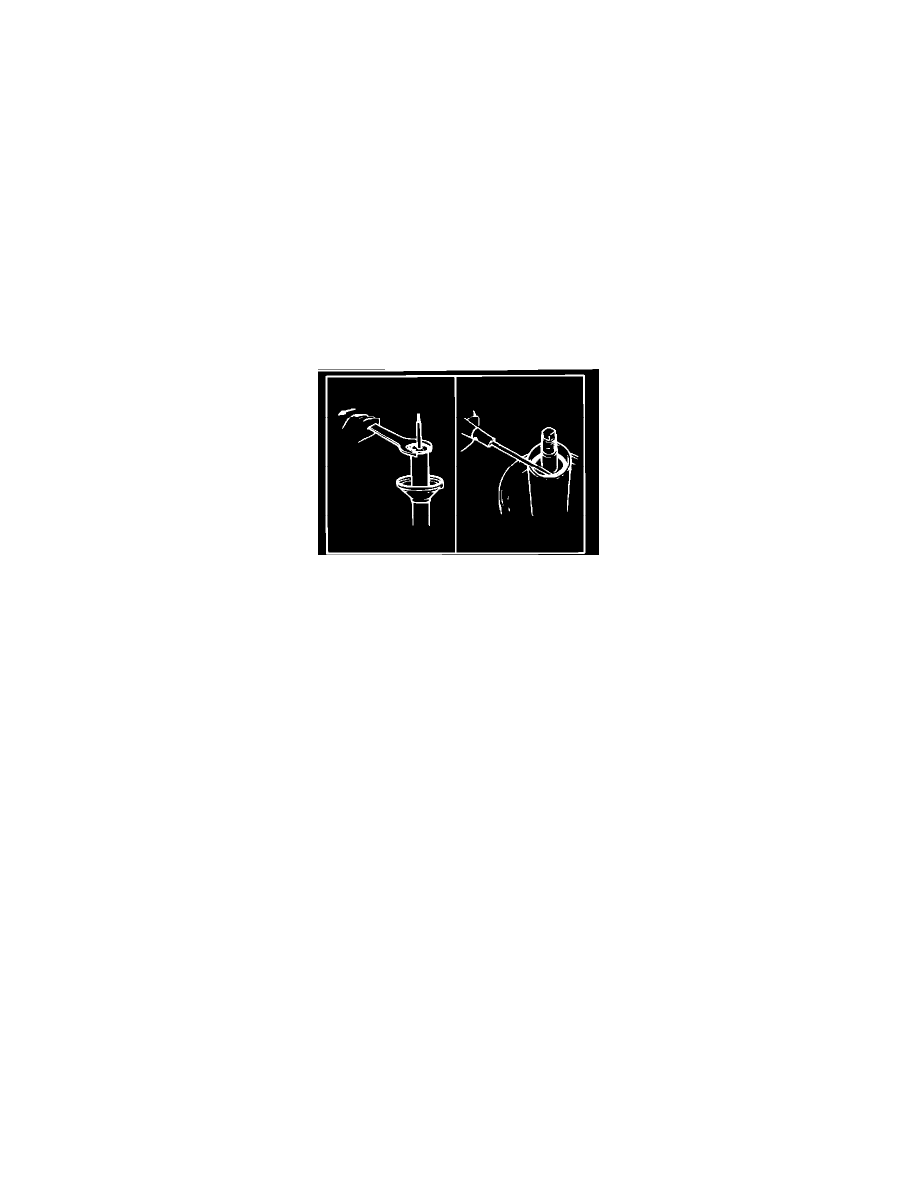
Fig. 1 Removing cap nut, seal and O-ring from reservoir tube
3.
Remove cap nut and seal assembly from reservoir tube, then pry O-ring from piston rod guide, Fig. 1.
4.
Pulling upward, remove piston rod and pressure tube assembly from reservoir tube. Do not remove base valve from pressure tube or piston
from piston rod.
Inspection
Inspect reservoir tube and mounting block for damage or wear, thrust bearing for roughness, coil spring for signs of fatigue and cap nut and seal
assembly for damaged threads or seal lip. Replace, if necessary.
Assembly
A cartridge type replacement damper is available. If this replacement damper is used, proceed to Step 6.
1.
Install pressure tube and piston rod into reservoir tube.
2.
Fill reservoir tube with 225cc of shock absorber fluid.
3.
Position new O-ring between piston rod guide and reservoir tube, then apply grease to oil seal lip.
4.
Install cap nut and oil seal assembly and partially tighten cap nut.
5.
Extend piston rod to its maximum length, then lower and torque cap nut to 36-43 ft.lbs.
6.
If using cartridge type damper, install cartridge and torque cap nut to 58-108 ft.lbs.
7.
Position bumper stop and dust boot onto piston rod, then compress coil spring. Install spring, spring seat, thrust bearing, thrust bearing seat and the
mounting block. Install washer and locknut, then partially tighten locknut.
Installation
Reverse removal procedure to install. Align marks on suspension tower and mounting block. Torque mounting block locknut to 47-59 ft.lbs., mounting
block to suspension tower attaching nuts to 17-22 ft.lbs. and steering knuckle to shock assembly retaining bolts to 51 ft.lbs.
After installing shock absorber assembly, measure clearance between floor and each headlight. The difference between each side should not exceed .590
inch. Adjust clearance differences by positioning adjusting plates onto mounting blocks. Do not use more than two adjusting plates at one side.