
RX7 2RTR- 1308cc 1.3L FI (1987)
Air Flow Meter/Sensor: Testing and Inspection
Air Flow Meter/Sensor
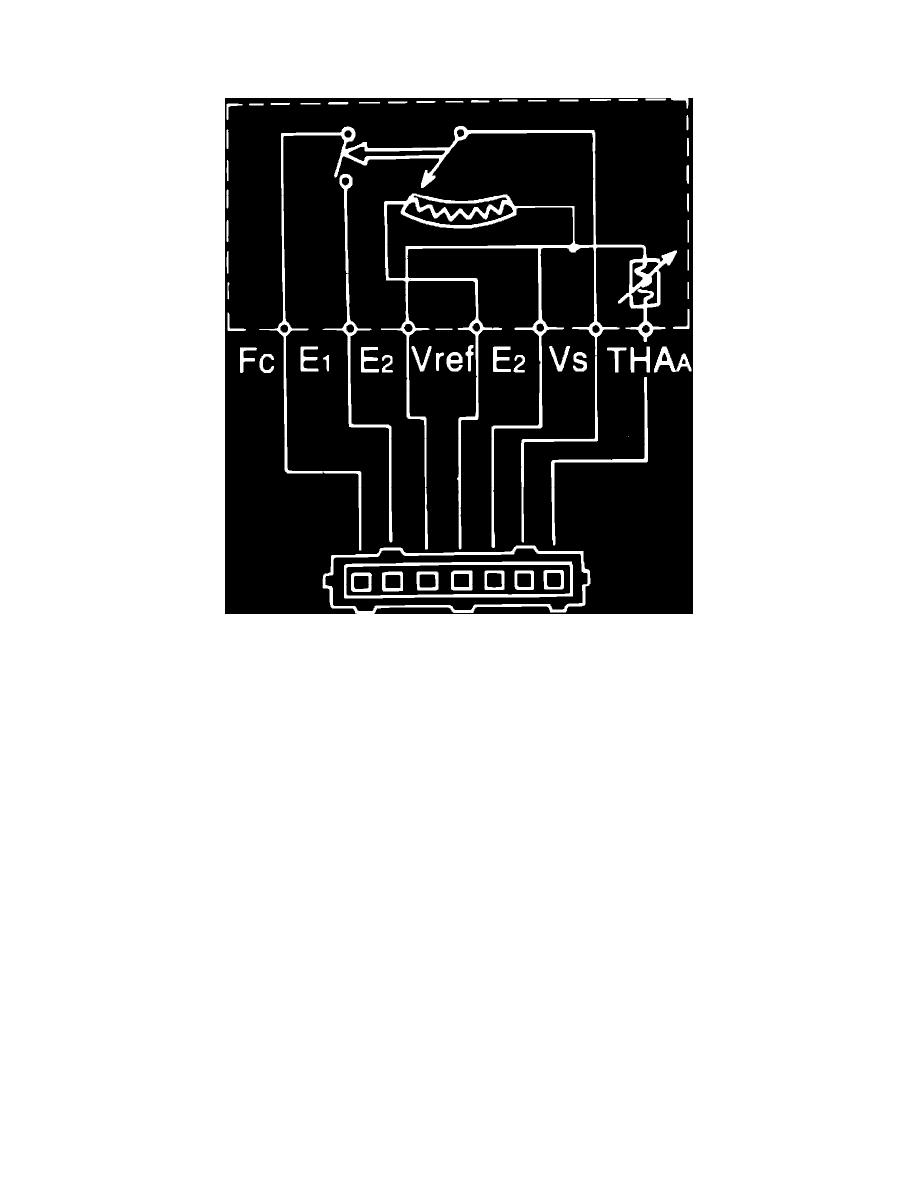
Fig. 29 Air flow meter terminal identification.
1.
Check air flow meter body for cracks or damage, replacing as necessary.
2.
Ensure measuring plate opens smoothly.
3.
Using ohmmeter, check resistance between terminals, Fig. 29, as follows:
a. Resistance between terminals E2 and VS should be 50-500 ohms.
b. Resistance between terminals E2 and Vref should be 200-500 ohms.
c. Resistance between terminals E2 and THAA should be 10,000-20,000 ohms at (-)4°F, 4000-7000 ohms at 32°F, 2000-3000 ohms at 68°F,
900-1300 ohms at 104°F and 400-700 ohms at 140°F.
d. Resistance between terminals E1 and FC should be infinite with measuring plate fully closed or zero with measuring plate fully open and, on
1988 models, resistance between terminals E2 and VS should be 50-500 ohms regardless of position of measuring plate.