
RX7 2RTR- 1308cc 1.3L FI (1987)
Crankshaft Position Sensor: Testing and Inspection
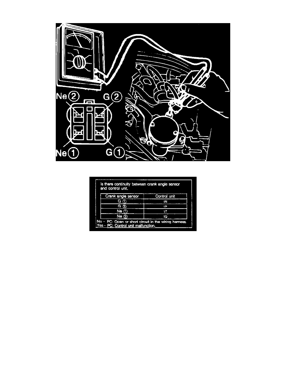
Fig. 79 Crank angle sensor connector terminal identification.
1.
Disconnect crank angle sensor connector.
2.
Connect circuit tester to terminals of crank angle sensor, Fig. 79.
3.
Ensure resistance is 110-210 ohms between terminals G1 and G2 and between terminals Ne1 and Ne2.