
RX7 2RTR- 1308cc 1.3L FI (1987)
Alignment: Service and Repair
Preliminary Checks
1.
Ensure tire pressure is as specified by manufacturer.
2.
Inspect ball joints and steering linkage for excessive looseness. Repair as required.
3.
Ensure vehicle is level and has no luggage or passenger load.
4.
Ensure difference in height from center of wheel to fender brim between right and left sides is equal.
Camber
FRONT
1.
Raise and support front of vehicle, then open hood.
2.
Remove four shock absorber mounting block to fender attaching nuts.
3.
Push mounting block downward and turn it until specified angles are obtained.
4.
Install four shock absorber mounting block to fender attaching bolts. Torque bolts to 22-27 ft.lbs. on 1984-87 models, 29-43 ft.lbs. on 1988 RX-7
and 34-46 ft.lbs. on 1988 626 and MX-6.
REAR
Camber is not adjustable and is set to specifications during production. Whenever camber is moved out of specified angle, check all parts of rear
suspension and body alignment. Repair or replace defective part(s) as required.
Caster
1.
Raise and support front of vehicle, then open hood.
2.
Remove four shock absorber mounting block to fender attaching nuts.
3.
Push mounting block downward and turn it until specified angles are obtained.
4.
Install four shock absorber mounting block to fender attaching bolts. Torque bolts to 22-27 ft.lbs. on 1984-87 models, 29-43 ft.lbs. on 1988 RX-7
and 34-46 ft.lbs. on 1988 626 and MX-6.
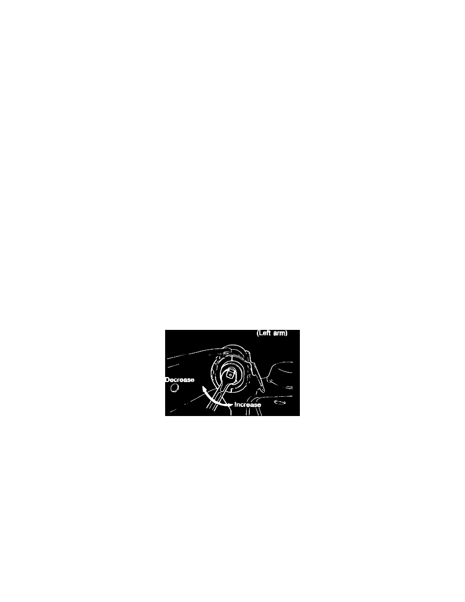
Distance From Subframe to Lateral Link Ball Joint
Fig. 6 Adjusting distance from subframe to lateral link ball joint. 1986-88 RX-7
Measure the distance between the center of the subframe rubber mount and the center of the lateral link ball joint for both left and right of vehicle. If
measurements obtained are within .2 inch or each other, distance is correct. If not, adjust as follows:
1.
To increase the distance, turn adjusting cam as follows:
a. Right arm-turn adjusting cam clockwise, Fig. 6.
b. Left arm-turn adjusting cam counterclockwise, Fig. 6.
2.
To decrease the distance, turn adjusting cam as follows:
a. Right arm-turn adjusting cam counterclockwise, Fig. 6.
b. Left arm-turn adjusting cam clockwise, Fig. 6. Amount of trailing arm movement is .07 inch.
King Pin Inclination
King pin inclination is not adjustable and is set to specifications during production. Whenever king pin inclination is moved out of specified angle, check
all parts of front suspension and body alignment. Repair or replace defective part(s) as required.
Toe-In