
RX7 2RTR- 1308cc 1.3L Turbo FI (1989)
Hydraulic Control Assembly - Antilock Brakes: Testing and Inspection
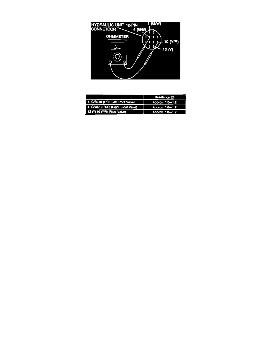
Fig. 48 Front & Rear Valve Terminal Identification.
Fig. 49 Front & Rear Valve Resistance Specification.
1.
Disconnect hydraulic unit 12 pin connector, then check resistance of terminals in Figs. 48 and 49.
2.
If resistance is as specified, check wiring harness between hydraulic unit and ABS control unit.