
RX7 2RTR- 1308cc 1.3L Turbo FI (1989)
Idle Speed/Throttle Actuator - Electronic: Description and Operation
Idle Speed Control System
To improve idle smoothness, the idle speed control (ISC) system controls the intake air amount by regulating the bypass air amount that passes
through the throttle body. The computerized engine control related components of the idle speed control system are the bypass air control valve (BAC),
accelerated warm-up system (AWS), and the control system.
During the warm up phase the engine receives more fuel due to the influence of the accelerated warm-up system (AWS). This is to overcome the
frictional resistance in the cold engine and to guarantee a stable idle speed.
There are increased frictional resistances present in a cold engine which must be overcome at idle speed. The engine is therefore allowed to take in
more air through the air valve by bypassing the throttle valve. Since this additional air is measured by the airflow sensor and is taken into account when
the fuel is metered, the engine receives more air/fuel mixture. With a cold engine a stable idle speed can therefore be achieved.
The bypass air control valve (BAC) is used to regulate the idle speed and keep it within a set range. The valve accomplishes this by regulating the
amount of air that is allowed to bypass the throttle plates. As the idle speed varies out of the specified range, the idle speed control valve increases the
passage size, if the idle speed is too low, or decreases the passage size, if the idle speed is too high. Since this adjustment of airflow is measured by the
airflow sensor and is taken into account when the fuel is metered, the proper air/fuel mixture is maintained throughout any idle speed adjustments.
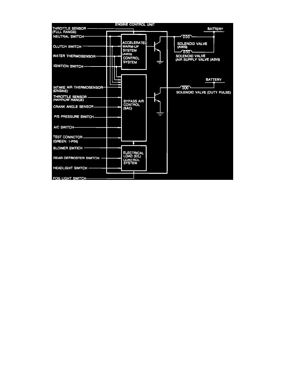
The control system consists of the throttle sensor, engine control unit (ECU), clutch switch, neutral switch, intake air thermosensor, crank angle sensor
, A/C switch, blower switch, rear defroster switch, headlight switch, fog light switch, water thermosensor, and the power steering pressure switch. These
components act together to control the idle speed.
The throttle sensor is a potentiometer splined to the throttle shaft. The potentiometer rotates with the shaft as the throttle plates open and close. The
varying resistance of the potentiometer alters the reference voltage emitted from the engine control unit (ECU) and creates a signal for use as input by the
ECU. The ECU receives inputs from the various inputs and determines the proper idle speed for the engine. The crank angle sensor detects the
eccentric shaft angle at 30° intervals and front rotor position, then sends a signal to the ECU. The ECU detects additional engine load when signals from
the A/C switch, blower switch, rear defroster switch, headlight switch, and fog light switch are received. The intake air thermosensors detects intake air
temperature and sends a signal to the engine control unit. One thermosensor is installed in the air flow meter, and the other is located in the air intake
pipe. The clutch switch detects in-gear condition and sends a signal to the control unit. The switch closes when the clutch pedal is released. The neutral
switch detects in gear condition and sends a signal to the engine control unit. The switch is on when the transmission is in gear. The power steering
pressure switch detects power steering operation and sends a signal to the engine control unit. The switch is closed when the steering wheel is turned.
The water thermosensor detects coolant temperature and sends a signal to the engine control unit.