
RX7 2RTR- 1308cc 1.3L Turbo FI (1989)
1.
Disconnect two prong connector and connect a voltmeter in series with one side of the connectors.
2.
Turn ignition switch "ON." Check that meter reads approximately 12V.
3.
Turn ignition switch "OFF" and disconnect voltmeter and negative battery cable.
4.
Reconnect the two prong connector.
5.
Disconnect the four prong connector and connect igniter checker (Mazda SST #49 F018 002 or aftermarket equivalent) to four prong connector and
coil/igniter assembly.
CAUTION:To avoid component damage, disconnect the negative battery cable before removing the "B" or "L" wires from the coil/igniter
assembly. Do not disconnect "Br" wire from coil. To avoid shock hazard during this test, high tension leads must remain connected to
the coil.
6.
Disconnect "B" and "L" wires from coil/igniter assembly.
7.
Reconnect negative battery cable.
8.
Connect ohmmeter negative lead to "B" wire and positive lead to ground.
9.
Turn ignition switch "ON."
10. Set igniter checker switch "SW1" to position "T1." Push "SW2" up while observing ohmmeter. Needle should jump to approximately one third on
the X1 scale and then return.
11. Turn ignition switch "OFF" and disconnect ohmmeter.
12.
Connect ohmmeter negative lead to "L" wire and positive lead to ground.
13. Turn ignition switch "ON."
14. Set igniter checker switch "SW1" to position "T2." Push "SW2" up while observing ohmmeter. Needle should jump to approximately one third on
the X1 scale and then return.
15. If not as specified, replace igniter.
COIL
Trailing Side Coil Testing
1.
Disconnect negative battery cable.
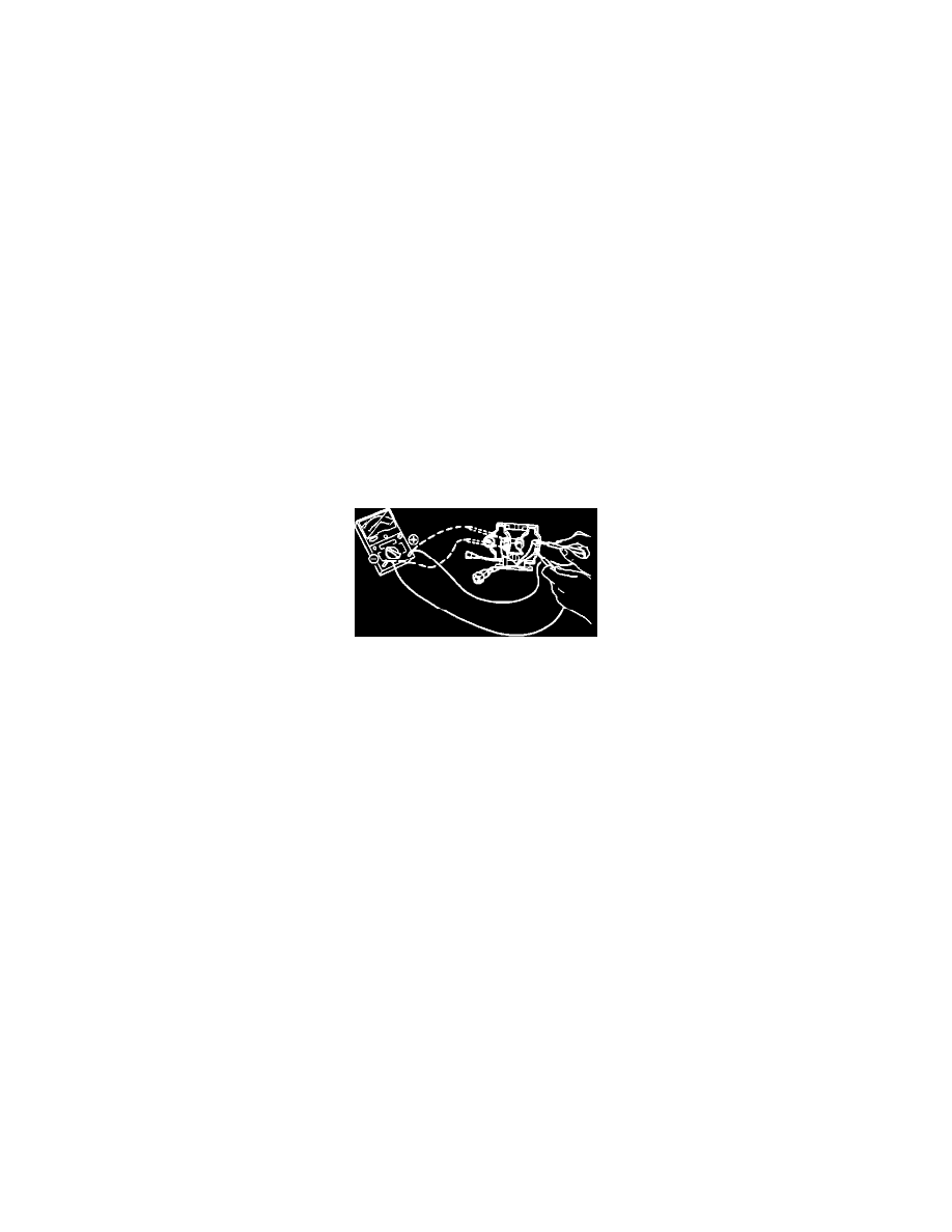
2.
Check coil resistance as shown on image. It should read below 1 ohm.
3.
If not as specified, replace coil.