
Tribute 2WD L4-2.5L (2009)
16. Install the ACL assembly.
a. Install the ACL assembly bracket bolt.
i.
Tighten to 10 Nm {1.0 kgf-m, 89 in-lbf}.
b. Connect the MAF sensor electrical connector.
c. Connect the brake booster vacuum hose to the ACL outlet pipe.
d. Attach the wiring harness fastener to the ACL assembly.
e. Connect the engine breather to the ACL assembly.
f.
Tighten the ACL outlet pipe clamp at the TB.
i.
Tighten to 5 Nm {0.5 kgf-m, 44 in-lbf}.
17. Fill with clean transaxle fluid to the correct level.
18. Download a new solenoid body strategy to the PCM. See See: Transmission Control Systems/Description and Operation.
19. Using the scan tool, select module programming and programmable parameters under the tool box icon and select transmission. Follow the
instructions displayed on the scan tool.
There are fields to enter the solenoid body 7-digit identification and 13-digit strategy recorded from the solenoid body.
20. The scan tool will verify that the numbers entered are valid and display a message if the information is not valid. The scan tool checks to see if the
file is present on the scan tool. If the file is present, the technician may proceed with downloading the file to the PCM. If the file is not present, the
scan tool will need to be connected to the Professional Technician Society (PTS) server to download the file onto the scan tool.
21. Verify that the file is present on the scan tool. If the file is present, go to Step 8. If the file is not present, continue with this procedure.
22. Connect the scan tool to the PTS sever. The screen will display a progress bar when connecting to the network.
23. Follow the instructions on the network to download the strategy file to the scan tool. The screen will display a progress bar when downloading the
strategy file to the scan tool and display a message if it is downloaded successfully.
24. If the scan tool cannot be connected to the PTS server, contact the National Hotline.
NOTE:If the scan tool cannot download a strategy from the web site, a partial strategy will automatically be downloaded.
25. Reconnect the scan tool to the vehicle.
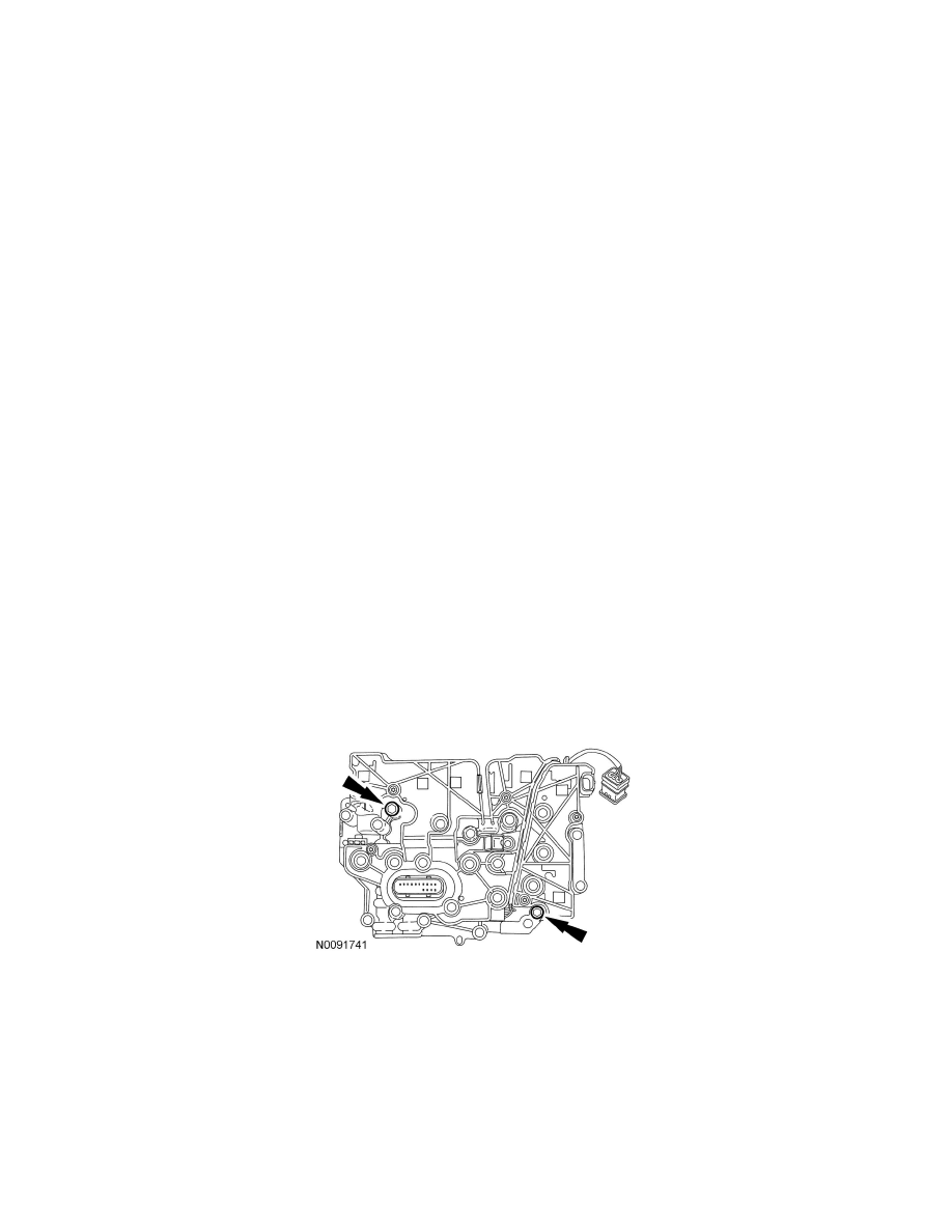
26. Install the solenoid body onto the main control valve body. Install the 2 bolts.
-
Tighten to 10 Nm {1.0 kgf-m, 89 in-lbf}.
27. If a new solenoid body was installed, compare the 7-digit identification and the 13-digit strategy fields from the solenoid body to the replacement
solenoid body tag provided with the solenoid body service kit and place it over the existing identification tag.
The scan tool will automatically download the strategy file or partial strategy file to the PCM and will display a progress bar while downloading.
The scan tool will display a message when it is finished downloading the data that states that the file was downloaded successfully.
Solenoid Body Leadframe Removal/Installation
SOLENOID BODY LEADFRAME REMOVAL/INSTALLATION