
Tribute 4WD L4-2.3L Hybrid (2008)
Driver/Vehicle Information Display: Pinpoint Tests
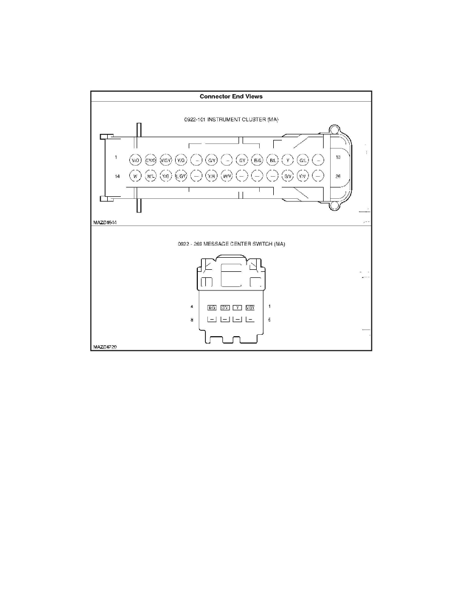
Connector End Views - Information And Message Center
--
CONNECTOR END VIEWS - INFORMATION AND MESSAGE CENTER - HYBRID
Pinpoint Test 1: The Message Center Is Not Operating Correctly
-
PINPOINT TEST 1: THE MESSAGE CENTER IS NOT OPERATING CORRECTLY - HYBRID
Normal Operation
The message center is located in the center of the instrument cluster between the tachometer and the speedometer in the vacuum fluorescent display area.
The message center is integral to the instrument cluster and uses the same voltage supply as the instrument cluster. The RUN/START voltage is supplied
to the instrument cluster on circuit (W/V) and the keep alive B+ voltage is received on circuit (Y/R). The instrument cluster logic ground is through
circuit (B/G) and the bulb ground is through circuit (B/L).The message center functionality is controlled through the message center switch, which is
hardwired to the instrument cluster through input circuit (G/V) and return circuit (Y). There are 3 message center switch buttons with each button
operating a switch that uses different resistance values. The instrument cluster sends out a reference voltage to the message center switch on the input
circuit (G/V) and monitors the voltage drop when a message center switch button is pressed. The voltage drop varies based upon the resistance of each
button, providing a specific indication to the instrument cluster which switch is pressed.
-
DTC B1206 (EIC Switch-1 Assembly Circuit Open) - a continuous and on-demand DTC that sets when the instrument cluster detects an open on
the message center switch input, circuit (G/V).
-
DTC B1208 (EIC Switch-1 Assembly Circuit Short to Ground) - a continuous and on-demand DTC that sets when the instrument cluster detects a
short to ground on the message center switch input, circuit (G/V).
Possible Causes
-
Wiring, terminals or connectors
-
Message center switch
-
Instrument cluster