
Tribute 4WD L4-2.3L Hybrid (2008)
License Plate Lamp: Initial Inspection and Diagnostic Overview
PARKING, REAR AND LICENSE PLATE LAMPS
See the Tribute Wiring Diagram for schematic information.
Inspection and Verification
1. Verify the customer concern.
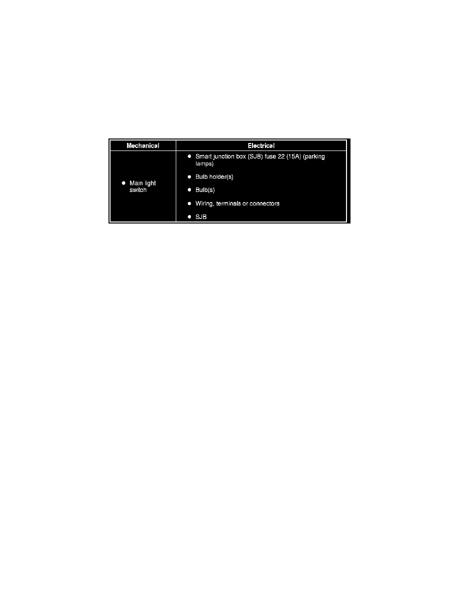
2. Visually inspect for obvious signs of mechanical or electrical damage.
Visual Inspection Chart
3. If an obvious cause for an observed or reported concern is found, correct the cause (if possible) before proceeding to the next step.
NOTE: Make sure the main light switch is in the OFF position.
NOTE: Make sure the multi-function switch is in the LOW BEAM position.
4. If the cause is not visually evident, connect the scan tool to the data link connector (DLC).
NOTE: Make sure to use the latest scan tool software release.
5. If the scan tool does not communicate with the VCM:
-
Check the VCM connection to the vehicle.
-
Check the scan tool connection to the VCM.
-
See See: Powertrain Management/Computers and Control Systems/Testing and Inspection/Pinpoint Tests/CAN Communication
Network/Pinpoint Test 1: The PCM Does Not Respond To The Scan Tool Or No High Speed Controller Area Network (HS-CAN)
Communication, to diagnose no communication with the scan tool.
NOTE: The vehicle communication module (VCM) LED prove-out confirms power and ground from the DLC are provided to the VCM.
6. If the scan tool does not communicate with the vehicle:
-
Verify the ignition key is in the ON position.
-
Verify the scan tool operation with a known good vehicle.
-
See See: Powertrain Management/Computers and Control Systems/Testing and Inspection/Pinpoint Tests/CAN Communication
Network/Pinpoint Test 1: The PCM Does Not Respond To The Scan Tool Or No High Speed Controller Area Network (HS-CAN)
Communication, to diagnose no response from the PCM.
7. Carry out the network test:
-
If the scan tool responds with no communication for one or more modules, see - See: Powertrain Management/Computers and Control
Systems/Testing and Inspection/Initial Inspection and Diagnostic Overview/Communications Network - Troubleshooting.
-
If the network test passes, retrieve and record the continuous memory DTCs.
8. Clear the continuous DTCs and carry out the self-test diagnostics for the smart junction box (SJB).
9. If the DTCs retrieved are related to the concern, go to the Smart Junction Box (SJB) DTC Chart. See: Powertrain Management/Computers and
Control Systems/Testing and Inspection/Diagnostic Trouble Code Descriptions/Parking, Rear and License Plate Lamps - DTC Chart For all other
DTCs, see - See: Powertrain Management/Computers and Control Systems/Testing and Inspection/Diagnostic Trouble Code
Descriptions/Diagnostic Trouble Code (DTC) Chart - B, C, P And U Codes.