
Tribute 4WD L4-2.3L Hybrid (2008)
2. Working under the vehicle, install an accelerometer. The accelerometer can be attached and mounted near either the transaxle or differential end of
the driveshaft.
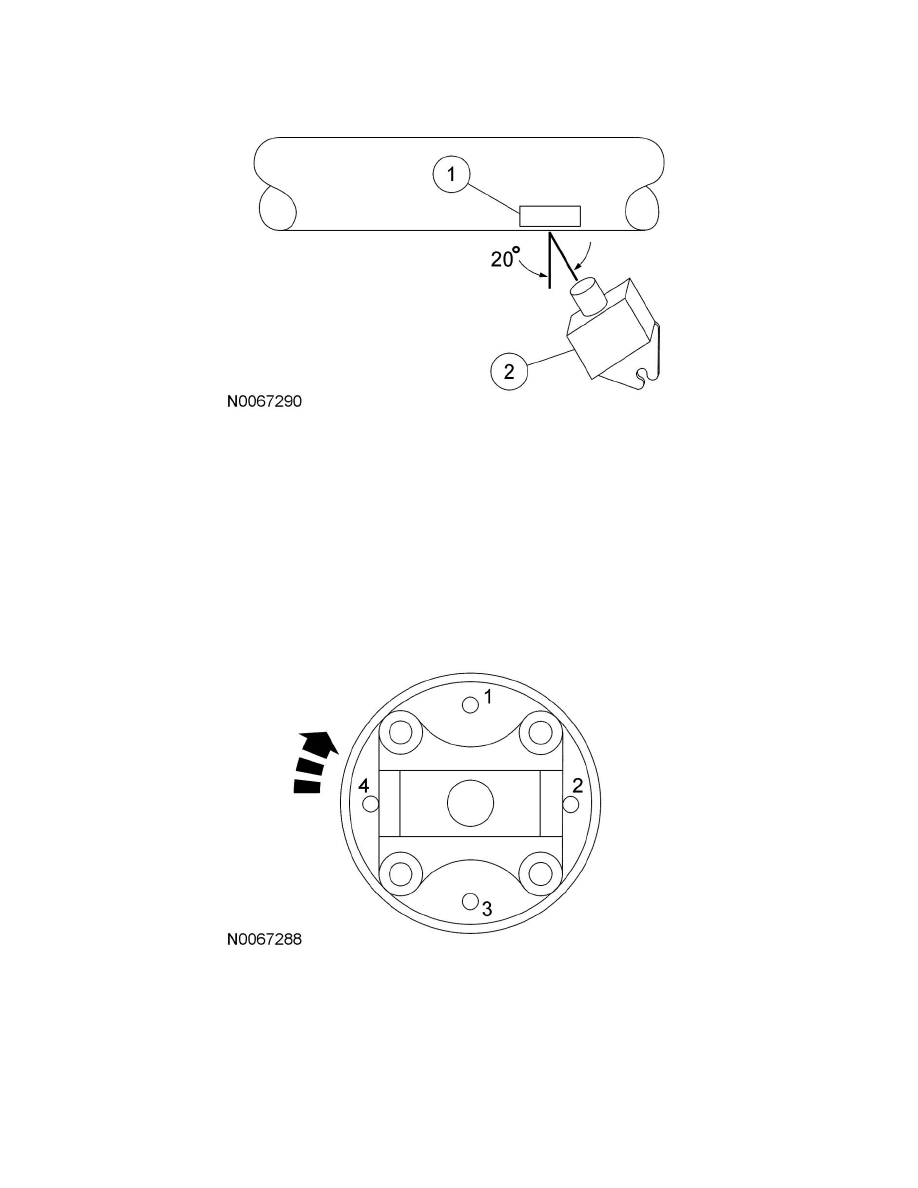
3. Clean an area of the driveshaft and install the reflective tape, then install the photo-tachometer sensor. The sensor should be placed at
approximately a 20-degree angle perpendicular to the surface of the reflective tape. Make sure the sensor does not get moved during the balance
procedure.
a. Reflective tape.
b. Photo-tachometer sensor.
4. Using the Mastertech(R) Series MTS 4000 Driveline Balance and NVH Analyzer (Vetronix), run a driveshaft balance test with the driveshaft
unmodified.
Vehicles with tapped pinion flanges
1. Label the tapped holes in the pinion flange numerically, starting at the top hole as 1. Mark the remaining holes 2, 3 and 4. Label in the direction of
rotation.
2. Using the Mastertech(R) Series MTS 4000 Driveline Balance and NVH Analyzer (Vetronix), run a second test with the 12 mm (0.47 in) test
weight set screw in the No. 1 hole, previously marked on the pinion flange.