
Capri L4-1597cc 1.6L DOHC (1992)
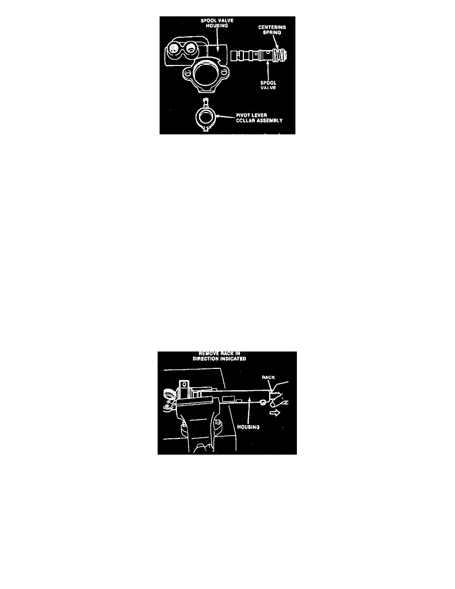
Fig. 3 Exploded View Of Valve Body
DISASSEMBLE
1.
Position steering gear in a soft jawed vise.
2.
Disconnect valve body to steering gear hydraulic tubes, Fig. 1.
3.
Remove steering gear mounting brackets and bushings.
4.
Using two screwdrivers and a self tapping screw, remove brass tubing seats from steering gear housing, Fig. 2.
5.
Using a suitable cold chisel, remove pinion shaft dust boot.
6.
Using a No. 40 Torx bit, remove valve body attaching bolts and valve body.
7.
Wrap cloth around valve body, then position valve body in vise.
8.
Remove valve body end plug, then remove pivot lever collar, Fig. 3.
9.
Using a suitable punch in pivot lever hole, slide spool valve part way out of valve body.
10.
Carefully remove spool valve from valve body, then remove spool valve O-ring.
11.
Place alignment marks on tie rods, jam nuts and tie rod ends so they can be installed in the same position.
12.
Remove tie rod ends and jam nuts from tie rods.
13.
Remove tie rod boots from steering gear housing.
14.
Using a suitable cold chisel, uncrimp tie rod washer tabs.
15.
Position rack in a soft jawed vise, then using a suitable wrench, remove tie rods from rack.
16.
Loosen locknut, then remove adjusting plug, spring and yoke from steering gear.
17.
Protect outer bulkhead with a cloth, then remove outer bulkhead using a pipe wrench.
18.
Remove O-ring from outer bulkhead and discard.
19.
Pull pinion shaft assembly out through lower bearing side of steering gear housing.
20.
Using a wooden dowel, drive upper pinion bearing out of housing.
Fig. 4 Removing Rack From Steering Gear Housing
21.
Remove rack from steering gear housing in direction indicated in Fig. 4.
22.
Using tool No. T87C-3504-A, remove rack inner guide and seal.
INSPECTION
Check rack and pinion teeth for wear and damage. Position rack in V-blocks and check run-out using a suitable dial indicator. Rack run-out should not
exceed .012 inch. Check pinion bearing for looseness and wear. If rack, pinion or pinion bearings are found to be unsatisfactory, the rack and pinion
must be replaced as a set.