
Capri V8-302 5.0L (1982)
Intake Manifold: Service and Repair
Fig. 4 Cylinder Head Tightening Sequence
V8-255 & 302 ENGINES
Less E.F.I.
1.
Disconnect battery ground cable, then drain cooling system into suitable container.
2.
Remove air cleaner, crankcase ventilation hose and air cleaner inlet duct.
3.
Disconnect automatic choke heat tube, then the accelerator cable and cruise control linkage (if equipped) from carburetor. Remove accelerator
cable bracket.
4.
Disconnect vacuum hoses at intake manifold, then the ignition coil primary and secondary wiring.
5.
Disconnect spark plug wiring from spark plugs, then remove spark plug wiring and bracket assemblies from rocker arm cover studs. Remove
distributor cap adapter and secondary wiring as an assembly.
6.
Remove fuel line from carburetor and fuel pump.
7.
Disconnect distributor vacuum hose (if equipped), then the distributor wiring connector. Remove distributor hold-down bolt, then the distributor.
8.
Disconnect radiator hose from coolant outlet housing, then remove coolant temperature sensor wire.
9.
Disconnect heater hose from intake manifold, then the water pump bypass hose.
10.
Remove PCV valve from rocker arm cover.
11.
Remove the intake manifold attaching bolts, then the intake manifold and carburetor as an assembly. It may be necessary to pry the intake
manifold from the cylinder heads. If prying is necessary, use caution to avoid damaging gasket sealing surfaces.
12.
Reverse procedure to install, noting the following:
a. Clean all cylinder head/block to intake manifold contact areas.
b. Apply {1/8} bead of silicone sealer D6AZ-19562-B or equivalent to each corner where the cylinder heads joins the cylinder block.
c. Position replacement gaskets and seals on cylinder heads and block. Ensure gaskets are interlocked with tab locks on seals.
d. Apply {1/16} bead of silicone sealer D6AZ-19562-B or equivalent to each end where the intake manifold gaskets join the cylinder block
seals. Do not drip any sealer into engine lifter galley.
e. Install intake manifold carefully to avoid smearing gasket compound. Run a finger around the seal area to ensure seals are properly in
place.
f.
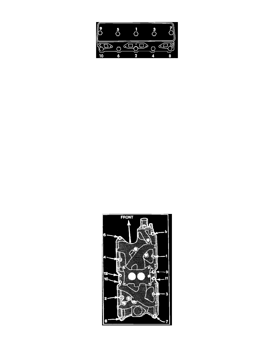
Torque bolts in sequence, Fig. 17, to 24 ft. lbs.
Fig. 13 Intake manifold tightening sequence. V8-255, 302 & V8-351W