
Capri V8-302 5.0L (1982)
Positive Crankcase Ventilation Valve: Description and Operation
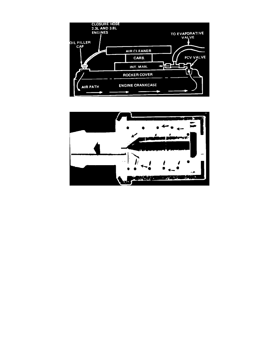
Fig. 55 Typical PCV system
Fig. 56 PCV valve
All engines produce small amounts of blow-by gases which seep past the piston rings and into the crankcase. These blow-by gases are the result of
the high pressures developed within the combustion chamber during the combustion process, and contain undesirable pollutants. To prevent
blow-by gases from entering the atmosphere while allowing proper crankcase ventilation, all engines use a PCV system, Fig. 55.
The PCV system prevents blow-by gases from escaping by routing them through a vacuum controlled ventilating valve and a hose into the intake
manifold. The blow-by gases mix with the air/fuel mixture and are burned in the combustion chambers. When the engine is running, fresh air is
drawn into the crankcase through a tube or hose connected to the air cleaner housing.
The PCV valve, Fig. 56, consists of a needle valve, spring and housing. When the engine is off, the spring holds the needle valve closed to stop
vapors from entering the intake manifold. When the engine is running, manifold vacuum unseats the valve allowing crankcase vapors to enter the
intake manifold. In case of a backfire in the intake manifold the valve closes, stopping the backflow and preventing ignition of fumes in the
crankcase. During certain engine conditions, more blow-by gases are created than the ventilator valve can handle. The excess is returned through
the air intake tube to the air cleaner and carburetor where it is burned in the engine.